Download PDF
Download page Defining Ineffective Flow Areas.
Defining Ineffective Flow Areas
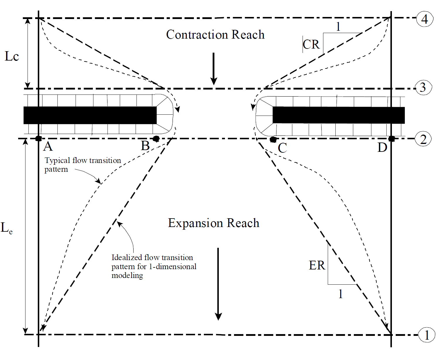
A basic problem in defining the bridge data is the definition of ineffective flow areas near the bridge structure. Referring to the figure below, the dashed lines represent the effective flow boundary for low flow and pressure flow conditions. Therefore, for cross sections 2 and 3, ineffective flow areas to either side of the bridge opening (along distance AB and CD) should not be included as part of the active flow area for low flow or pressure flow.
The bridge example shown in the figure below is a typical situation where the bridge spans the entire floodway and its abutments obstruct the natural floodplain. This is a similar situation as was shown in plan view in the figure above. The cross section numbers and locations are the same as those discussed in the "Cross Section Locations" section of this chapter. The problem is to convert the natural ground profile at cross sections 2 and 3 from the cross section shown in part B to that shown in part C of the figure below. The elimination of the ineffective overbank areas can be accomplished by redefining the geometry at cross sections 2 and 3 or by using the natural ground profile and requesting the program's ineffective area option to eliminate the use of the overbank area (as shown in part C of the figure below). Also, for high flows (flows over topping the bridge deck), the area outside of the main bridge opening may no longer be ineffective, and will need to be included as active flow area. If the modeler chooses to redefine the cross section, a fixed boundary is used at the sides of the cross section to contain the flow, when in fact a solid boundary is not physically there. The use of the ineffective area option is more appropriate and it does not add wetted perimeter to the active flow boundary above the given ground profile.
The ineffective area option is used at sections 2 and 3 to keep all the active flow in the area of the bridge opening until the elevations associated with the left and/or right ineffective flow areas are exceeded by the computed water surface elevation. The program allows the stations and controlling elevations of the left and right ineffective flow areas to be specified by the user. Also, the stations of the ineffective flow areas do not have to coincide with stations of the ground profile, the program will interpolate the ground station.
The ineffective flow areas should be set at stations that will adequately describe the active flow area at cross sections 2 and 3. In general, these stations should be placed outside the edges of the bridge opening to allow for the contraction and expansion of flow that occurs in the immediate vicinity of the bridge. On the upstream side of the bridge (section 3) the flow is contracting rapidly. A practical method for placing the stations of the ineffective flow areas is to assume a 1:1 contraction rate in the immediate vicinity of the bridge. In other words, if cross section 3 is 10 feet from the upstream bridge face, the ineffective flow areas should be placed 10 feet away from each side of the bridge opening. On the downstream side of the bridge (section 2), a similar assumption can be applied. The active flow area on the downstream side of the bridge may be less than, equal to, or greater than the width of the bridge opening. As flow converges into the bridge opening, depending on the abruptness of the abutments, the active flow area may constrict to be less than the bridge opening. As the flow passes through and out of the bridge it begins to expand. Because of this phenomenon, estimating the stationing of the ineffective flow areas at cross section 2 can be very difficult. In general, the user should make the active flow area equal to the width of the bridge opening or wider (to account for flow expanding), unless the bridge abutments are very abrupt (vertical wall abutments with no wing walls).
The elevations specified for ineffective flow should correspond to elevations where significant weir flow passes over the bridge. For the downstream cross section, the threshold water surface elevation for weir flow is not usually known on the initial run, so an estimate must be made. An elevation below the minimum top-of-road, such as an average between the low chord and minimum top-of-road, can be used as a first estimate.
Using the ineffective area option to define the ineffective flow areas allows the overbank areas to become effective as soon as the ineffective area elevations are exceeded. The assumption is that under weir flow conditions, the water can generally flow across the whole bridge length and the entire overbank in the vicinity of the bridge would be effectively carrying flow up to and over the bridge.
Note
In general, when the ineffective flow areas turn off, and the overbank area of cross section 2 and 3 is free to move, the computed amount of conveyance (flow) in the overbank areas is too high compared to the flow going over the roadway in those same areas. This is due to the fact that in 1D modeling the flow distribution in each cross section is based only on that cross section and the Manning n values. So in order to reduce the conveyance in the overbank areas of cross section 2 and 3 to match more closely to the flow going over the roadway, modelers should increase the Manning's n values for the overbank areas of cross section 2 and 3. This will be a trial and error process, until the flow/conveyance of the overbank areas is constant with the flow hydraulics being calculated for the bridge in the overbank areas.
Cross section 3, just upstream from the bridge, is usually defined in the same manner as cross section 2. In many cases the cross sections are identical. The only difference generally is the stations and elevations to use for the ineffective area option. For the upstream cross section, the elevation should initially be set to the low point of the top-of-road. When this is done the user could possibly get a solution where the bridge hydraulics are computing weir flow, but the upstream water surface elevation comes out lower than the top of road. Both the weir flow and pressure flow equations are based on the energy grade line in the upstream cross section. Once an upstream energy is computed from the bridge hydraulics, the program tries to compute a water surface elevation in the upstream cross section that corresponds to that energy. Occasionally the program may get a water surface that is confined by the ineffective flow areas and lower than the minimum top of road. When this happens, the user should decrease the elevations of the upstream ineffective flow areas in order to get them to turn off. Once they turn off, the computed water surface elevation will be much closer to the computed energy gradeline (which is higher than the minimum high chord elevation).
Using the ineffective area option in the manner just described for the two cross sections on either side of the bridge provides for a constricted section when all of the flow is going under the bridge. When the water surface is higher than the control elevations used, the entire cross section is used. The program user should check the computed solutions on either side of the bridge section to ensure they are consistent with the type of flow. That is, for low flow or pressure flow solutions, the output should show the effective area restricted to the bridge opening. When the bridge output indicates weir flow, the solution should show that the entire cross section is effective. During overflow situations, the modeler should ensure that the overbank flow around the bridge is consistent with the weir flow.