Download PDF
Download page Energy Based Junction Method.
Energy Based Junction Method
The energy-based method solves for water surfaces across the junction by performing standard step calculations with the one dimensional energy equation
Case 1: Subcritical Flow - Flow Combining.
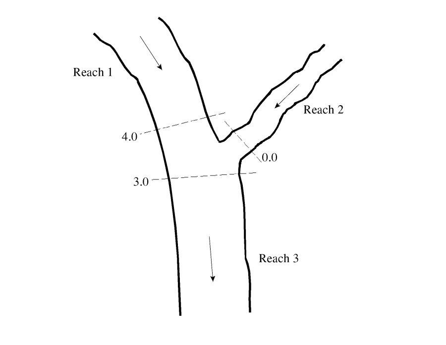
An example junction with flow combining is shown in the figure below. In this case, subcritical flow calculations are performed up to the most upstream section of reach 3. From here, backwater calculations are performed separately across the junction for each of the two upstream reaches. The water surface at reach 1, station 4.0 is calculated by performing a balance of energy from station 3.0 to 4.0. Friction losses are based on the length from station 4.0 to 3.0 and the average friction slope between the two sections. Contraction or expansion losses are also evaluated across the junction. The water surface for the downstream end of reach 2 is calculated in the same manner. The energy equation from station 3.0 to 4.0 is written as follows:

| 1) | \displaystyle WS_4 + \frac{\alpha _4 V^2_4}{2g} = WS_3 + \frac{\alpha _3 V^2_3}{2g} + L_{4-3} \overline{S} _{f_{4-3}} + C \left| \frac{\alpha _4 V^2_4}{2g} - \frac{\alpha _3 V^2_3}{2g} \right| |
Case 2: Subcritical Flow - Flow Split
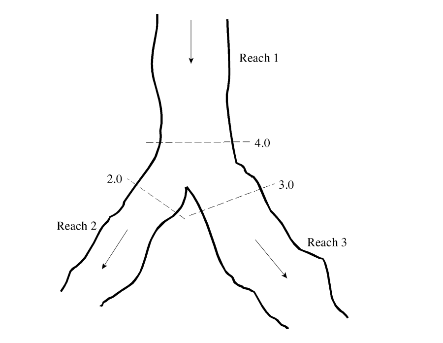
For this case, a subcritical water surface profile is calculated for both reaches 2 and 3, up to river stations 2.0 and 3.0 (see the figure below). The program then calculates the specific force (momentum) at the two locations. The cross section with the greater specific force is used as the downstream boundary for calculating the water surface across the junction at river station 4.0. For example, if cross section 3.0 had a greater specific force than section 2.0, the program will compute a backwater profile from station 3.0 to station 4.0 in order to get the water surface at 4.0. 
Currently the HEC-RAS program assumes that the user has entered the correct flow for each of the three reaches. In general, the amount of flow going to reach 2 and reach 3 is unknown. In order to obtain the correct flow distribution at the flow split, the user must perform a trial and error process. This procedure involves the following:
- Assume an initial flow split at the junction.
- Run the program in order to get energies and water surfaces at all the locations around the junction.
- Compare the energy at stations 2.0 and 3.0. If they differ by a significant magnitude, then the flow distribution is incorrect. Re-distribute the flow by putting more flow into the reach that had the lower energy.
- Run the program again and compare the energies. If the energy at stations 2.0 and 3.0 still differ significantly, then re-distribute the flow again.
- Keep doing this until the energies at stations 2.0 and 3.0 are within a reasonable tolerance.
Ideally it would be better to perform a backwater from station 2.0 to 4.0 and also from station 3.0 to 4.0, and then compare the two computed energies at the same location. Since the program only computes one energy at station 4.0, the user must compare the energies at the downstream cross sections. This procedure assumes that the cross sections around the junction are spaced closely together.
Case 3: Supercritical Flow - Flow Combining
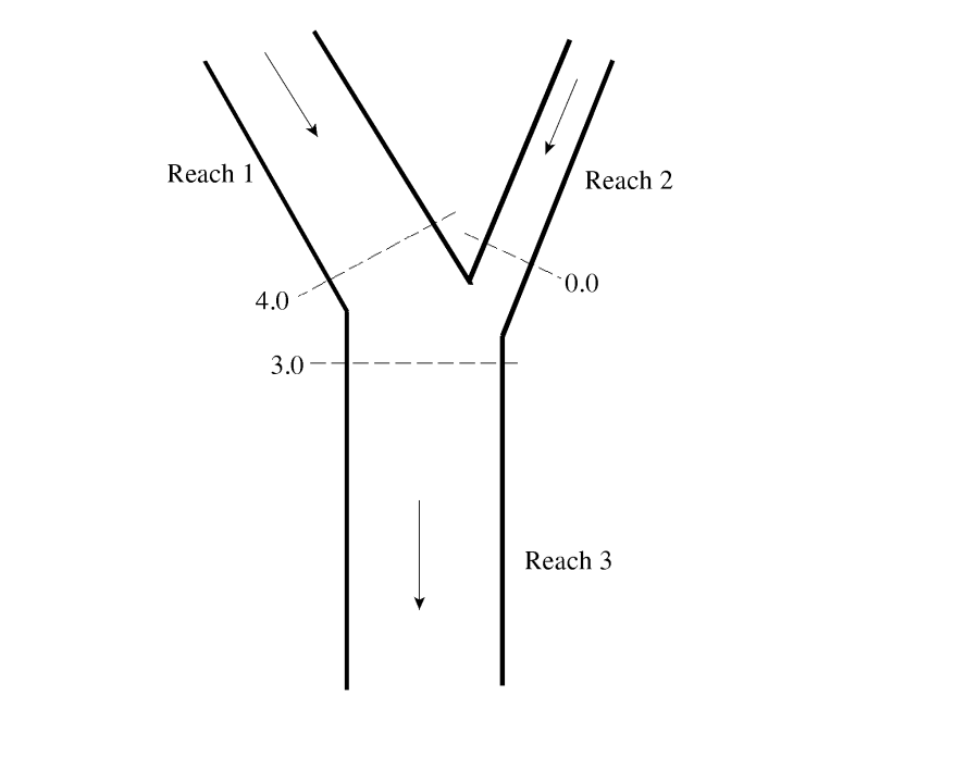
In this case, a supercritical water surface profile is calculated for all of reach 1 and 2, down to stations 4.0 and 0.0 (see the figure below). The program calculates the specific force at stations 4.0 and 0.0, and then takes the stream with the larger specific force as the controlling stream. A supercritical forewater calculation is made from the controlling upstream section down to station 3.0.

Case 4: Supercritical Flow - Flow Split
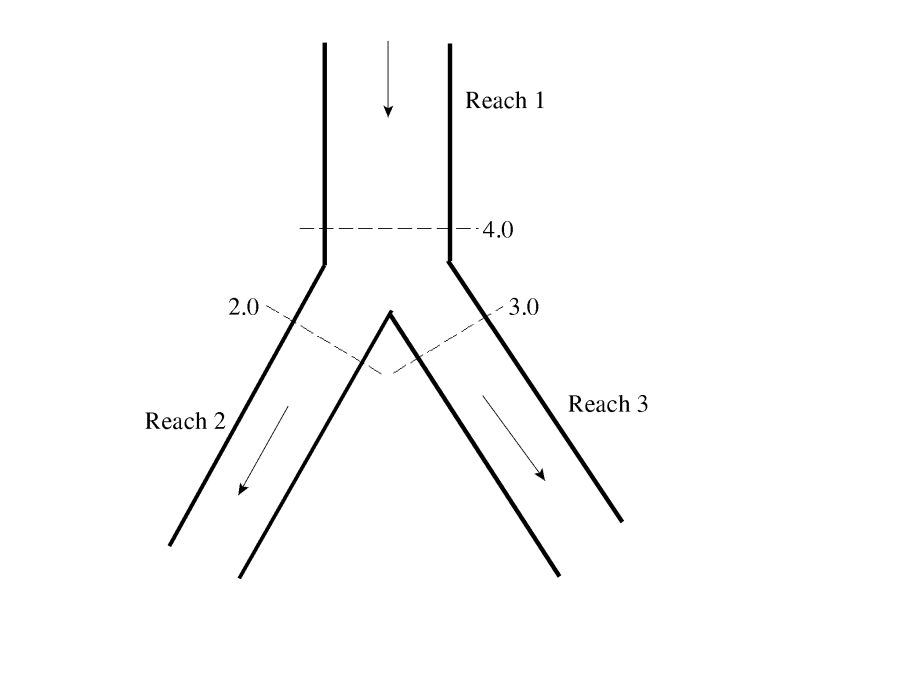
In this case a supercritical water surface profile is calculated down to station 4.0 of reach 1 (see the figure below). The water surfaces at sections 3.0 and 2.0 are calculated by performing separate forewater calculations from station 4.0 to station 2.0, and then from station 4.0 to 3.0.
Case 5: Mixed Flow Regime - Flow Combining
In the case of mixed flow, a subcritical profile calculation is made through the junction as described previously (see the figure below). If the flow remains subcritical during the supercritical flow calculations, then the subcritical answers are assumed to be correct. If, however, the flow at either or both of the cross sections upstream of the junction is found to have supercritical flow controlling, then the junction must be re-calculated. When one or more of the upstream sections is supercritical, the program will calculate the specific force of all the upstream sections. If the supercritical sections have a greater specific force than the subcritical sections, then the program assumes that supercritical flow will control. The program then makes a forewater calculation from the upstream section with the greatest specific force (let's say section 4.0) to the downstream section (section 3.0). 
The program next computes the specific force of both the subcritical and supercritical answers at section 3.0. If the supercritical answer at section 3.0 has a lower specific force than the previously computed subcritical answer, then the program uses the subcritical answer and assumes that a hydraulic jump occurred at the junction. If the supercritical answer has a greater specific force, then the program continues downstream with forewater calculations until a hydraulic jump is encountered. Also, any upstream reach that is subcritical must be recomputed. For example, if reach two is subcritical, the water surface at section 0.0 was based on a backwater calculation from section 3.0 to 0.0. If section 3.0 is found to be supercritical, the water surface at section 0.0 is set to critical depth, and backwater calculations are performed again for reach 2. If there are any reaches above reach 2 that are affected by this change, then they are also recomputed.
Case 6: Mixed Flow Regime - Split Flow

In this case, a subcritical profile through the junction is computed as described previously. If during the supercritical flow pass it is found that section 4.0 (figure above) is actually supercritical, the program will perform forewater calculations across the junction. The program will make a forewater calculation from section 4.0 to 2.0 and then from 4.0 to 3.0. The program will then calculate the specific force of the subcritical and supercritical answers at sections 2.0 and 3.0. Which ever answer has the greater specific force is assumed to be correct for each location. Normal mixed flow regime calculations continue on downstream from the junction.