Download PDF
Download page Effective Flow Length.
Effective Flow Length
Since friction losses are directly proportional to flow length, it becomes imperative to obtain the best possible estimate of flow length, especially for those cases where the friction loss is a significant component of the energy balance between two sections. For minor degrees of constriction, a straight line distance between cross sections is usually adequate. However, for more significant constrictions, this straight-line distance is representative of only that portion of the flow that is generally in direct line with the opening. Flow further away from the opening must flow not only downstream, but also across the valley to get to the opening, thus traveling much farther than the straight-line distance.
Schneider et al. (USGS, 1977) tabulated average streamline lengths for various approach section locations and various degrees of constriction. These results are not directly applicable in this model because they are derived for symmetric constrictions in channel reaches having uniform, homogeneous flow conveyance characteristics. Even if the exact solution algorithms were developed for non-symmetric, non-homogeneous conditions, the computer resource requirements for an exact solution are too great to warrant inclusion in the model. Therefore, a simplified computational technique was developed and incorporated into the model to compute average streamline length.
Schneider et al., defined the optimum location of the approach section as:
| 1) | \displaystyle L_{opt} = \frac{b}{\pi (1-m')} \phi |
Where Lopt is the distance, in ft, between the approach section and the upstream face of the bridge opening, b is the bridge opening width, and m' is the geometric contraction ratio computed by:
| 2) | \displaystyle m'=1- \frac{b}{B} |
Where B is the top width, in ft, of the approach section flow area. The Φ term in (1) is computed by:
| 3) | \displaystyle \phi = \frac{1}{2} ln \left[ \left( \sqrt{\frac{8}{\varepsilon ^2}+8} - \frac{3}{\varepsilon} - \varepsilon \right) \left( \sqrt{8+8 \varepsilon ^2} -3 \varepsilon - \frac{1}{\varepsilon} \right) \right] -ln \left( \varepsilon - \frac{1}{\varepsilon} \right) |
Where ε is computed by:
| 4) | \displaystyle \varepsilon = 1+ \delta + \sqrt{\delta ^2 + 2\delta} |
With δ computed as:
| 5) | \displaystyle \delta = \frac{2}{tan^2 \left[ \left( 1- \frac{b}{2B} \right) \pi \right]} |
Lopt is located in a zone of nearly one dimensional flow, thus satisfying the basic requirements of the one dimensional energy equation.
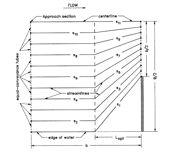
The simplified computational technique varies depending upon the relative magnitudes of Lopt and b. To introduce the technique, discussion is limited to the ideal situation of a symmetric constriction with uniform, homogeneous conveyance. For such conditions only one half of the valley cross-section is required. This one half section is divided into ten equal conveyance stream tubes between edge of water and the centerline at both the Lopt location and the upstream face of the bridge. Equal conveyance stream tubes are equivalent to equal flow stream tubes for one dimensional flow. The figure below illustrates a case with a small geometric contraction ratio. Lopt is less than b for lesser degrees of constriction. Since Lopt is located in a zone of nearly one dimensional flow, the streamlines are essentially parallel between the approach section and the Lopt location. Between Lopt and the bridge opening the corresponding flow division points are connected with straight lines. The effective flow length used by the model is the average length of the ten equal flow stream tubes computed by:
| 6) | \displaystyle L_{av} = \frac{1}{10} \left[ \sum_{i=2}^{10} S_i + \frac{(S_1 +S_{11} )}{2} \right] |
Where i indicates the streamline number and s is the individual streamline length. Although the straightline pattern is a gross simplification of the actual curvilinear streamlines, the computed Lav values are less than 2 percent smaller than the exact solution for small geometric contraction ratios.
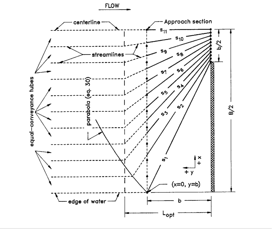
The figure below illustrates a relatively high degree of geometric contraction. Simply connecting the flow division points of the Lopt and bridge sections does not result in representative lengths for those streamlines furthest away from the opening.
Therefore, a parabola is computed by the equation:
| 7) | \displaystyle y^2 = 2b \left( x + \frac{b}{2} \right) |
This parabola has its focus at the edge of water and its axis in the plane of the upstream face of the bridge. Positive x and y distances are measured from the edge of water towards the stream centerline and upstream from the plane of the bridge, respectively. For portions of the section where Lopt is upstream from this parabola, the parallel streamlines are projected to the parabola and then a straight line connects this projected point with the corresponding flow division point in the bridge opening. Flow division points of the Lopt section at or downstream from the parabola are connected directly to their corresponding flow division point for the bridge opening. Only the distances between the approach and the cross section just upstream of the bridge opening are used to compute Lav with (5). This process generally produces results that are within 5 percent of the exact solution. For very severe constrictions (i.e., m' = 0.95), the differences are closer to 10 percent.

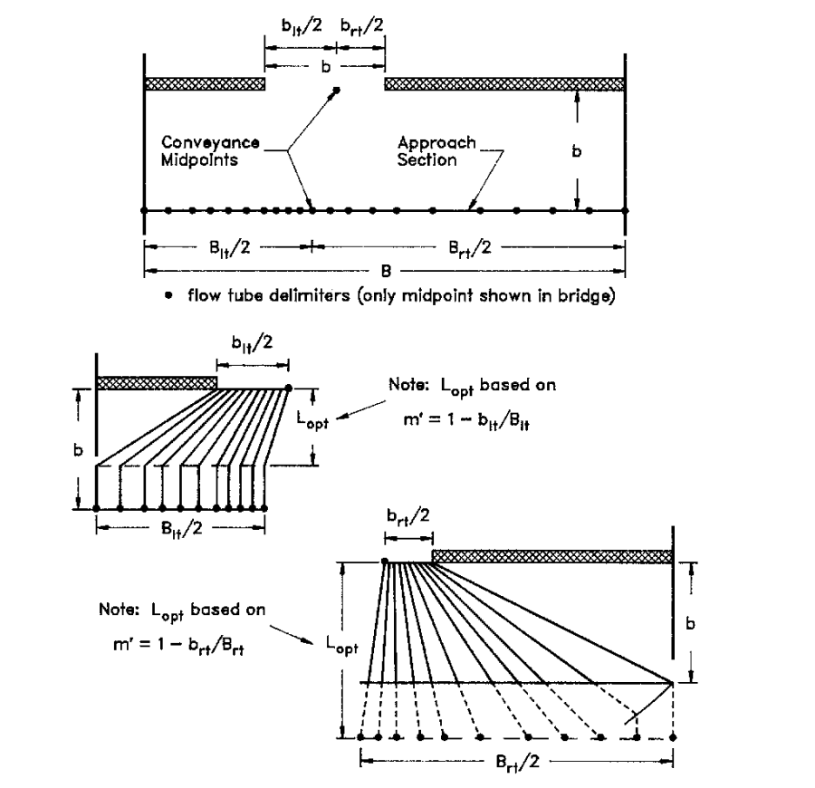
The non-uniform conveyance distribution in the approach reach is represented by defining the stream tubes on a conveyance basis. The model determines the horizontal stationing of 19 interior flow division points that subdivide both the Lopt and bridge sections into 20 tubes of equal conveyance. Asymmetric constrictions with nonuniform conveyances are analyzed by treating each half of the reach on either side of the conveyance midpoints separately, then averaging the results. Lav for each side provides the conveyance weighted average streamline length. The figure below illustrates a typical asymmetric, nonuniform conveyance situation. 