Download PDF
Download page Mixed Flow Regime Calculations.
Mixed Flow Regime Calculations
The HEC-RAS software has the ability to perform subcritical, supercritical, or mixed flow regime calculations for steady flow, 1D unsteady flow, and 2D unsteady flow modeling. For 1D steady flow the Specific Force equation is used in HEC-RAS to determine which flow regime is controlling, as well as locating any hydraulic jumps. The equation for Specific Force is derived from the momentum equation (Applications of the Momentum Equation:18). When applying the momentum equation to a very short reach of river, the external force of friction and the force due to the weight of water are very small, and can be ignored. The momentum equation then reduces to the following equation:
| 1) | \displaystyle \frac{Q^2_1 \beta _1}{gA_1} + A_1 \overline{Y} _1 = \frac{Q^2_2 \beta _2}{gA_2} + A_2 \overline{Y} _2 |
| Symbol | Description | Units |
|---|---|---|
Q | Discharge at each section | |
\beta | Momentum coefficient (similar to alpha) | |
A | Total flow area | |
\overline{Y} | Depth from the water surface to centroid of the area | |
g | Gravitational acceleration |
The two sides of the equation are analogous, and may be expressed for any channel section as a general function:
| 2) | \displaystyle SF = \frac{Q^2 \beta}{gA} + A \overline{Y} |
The generalized function (2) consists of two terms. The first term is the momentum of the flow passing through the channel cross section per unit time. This portion of the equation is considered the dynamic component. The second term represents the momentum of the static component, which is the force exerted by the hydrostatic pressure of the water. Both terms are essentially a force per unit weight of water. The sum of the two terms is called the Specific Force (Chow, 1959).
When the specific force equation is applied to natural channels, it is written in the following manner:
| 3) | \displaystyle SF = \frac{Q^2 \beta}{gA_m} + A_t \overline{Y} |
| Symbol | Description | Units |
|---|---|---|
A_m | Flow area in which there is motion | |
A_t | Total flow area, including ineffective flow areas |
The mixed flow regime calculations for steady flow analysis in HEC-RAS are performed as follows:
- First, a subcritical water surface profile is computed starting from a known downstream boundary condition. During the subcritical calculations, all locations where the program defaults to critical depth are flagged for further analysis.
- Next the program begins a supercritical profile calculation starting upstream. The program starts with a user specified upstream boundary condition. If the boundary condition is supercritical, the program checks to see if it has a greater specific force than the previously computed subcritical water surface at this location. If the supercritical boundary condition has a greater specific force, then it is assumed to control, and the program will begin calculating a supercritical profile from this section. If the subcritical answer has a greater specific force, then the program begins searching downstream to find a location where the program defaulted to critical depth in the subcritical run. When a critical depth is located, the program uses it as a boundary condition to begin a supercritical profile calculation.
- The program calculates a supercritical profile in the downstream direction until it reaches a cross section that has both a valid subcritical and a supercritical answer. When this occurs, the program calculates the specific force of both computed water surface elevations. Whichever answer has the greater specific force is considered to be the correct solution. If the supercritical answer has a greater specific force, the program continues making supercritical calculations in the downstream direction and comparing the specific force of the two solutions. When the program reaches a cross section whose subcritical answer has a greater specific force than the supercritical answer, the program assumes that a hydraulic jump occurred between that section and the previous cross section.
- The program then goes to the next downstream location that has a critical depth answer and continues the process.
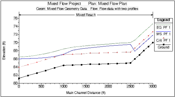
An example mixed flow profile, from HEC-RAS, is shown in the figure below. This example was adapted from problem 9-8, page 245, in Chow's "Open Channel Hydraulics" (Chow, 1959).
As shown in the figure above, the flow regime transitions from supercritical to subcritical just before the first break in slope.
For 1D and 2D modeling using the Finite Volume solution scheme, no special options are required to obtain mixed flow regime calculations. The finite volume solution scheme handles it directly. For the 1D finite difference solution scheme, the user must turn on a special mixed flow regime calculation mode. Please review the HEC-RAS User's manual for how to do mixed flow regime with the 1D Finite difference solution scheme to the unsteady flow equations.