Download PDF
Download page Downstream Storage, Tributaries, and Levees.
Downstream Storage, Tributaries, and Levees
Accounting for downstream storage in the floodplain below the dam is crucial in order to get a reasonable estimate of the flood wave propagation and attenuation as it moves downstream.
General floodplain storage (areas that get wet but have little to no velocity) can often be modeled as part of the normal cross section by using ineffective flow areas. If a portion of a cross section is wet, but it will have a very low velocity, using a high Manning's n values is another approach to modeling that area of the cross section.
Modeling Tributaries. Tributaries that come into the main river downstream may have flow reversals during the passing of the flood wave. Significant size tributaries need to be accounted for, since they may represent a large amount of storage volume taken out of the flood wave. Further, the resultant inundation maps will need to include the flooding extent up the tributaries. These factors require scrutiny when developing geometric data for HEC-RAS and can be addressed in four different ways when laying out data for tributaries. A tributary may be modeled using: (1) a separate river reach, (2) a 2D flow area, (3) a storage area, or (4) an extension of the main river cross sections.
The most comprehensive way to model the effects of a tributary to the main river is to model the tributary with cross sections or a 2D flow area. If the computed water surface along the tributary results in a sloped water surface, then modeling the tributary as a separate river reach is the preferred modeling method. Tributaries that have significant inflows to the overall flood hydrograph are strong candidates to be modeled as separate 1D reaches, or part of a 2D flow area that is being used to model the downstream area.
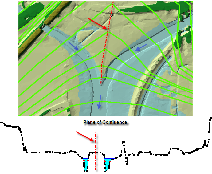
When adding a tributary to the main stem of a river, it is important to differentiate between the contributing area of the main stem cross sections versus the contributing area of the tributary cross sections. At the stream junction, if flow from the two reaches will mix, a decision will need to be made as to the line that represents the separation point of the tributary and the main stem flows. Cross sections from one reach should end just where the cross sections of the other reach begin, to insure complete inundation mapping. Cross sections should not overlap. The figure below depicts a tributary included in the model as a separate reach. As shown in the figure below, the user must identify the point at which to end the main stem cross sections and begin the tributary cross sections.
The next best option for accounting for tributary storage, is to model the tributary as a storage area, and connect the storage area to the main river with a lateral structure. The lateral structure can be a weir, in which the weir geometry is represented with a cross section from the tributary. This will allow water from the flood wave to back up and fill the storage area as a level pool of water. An example of modeling tributaries with storage areas and lateral structures is shown in the figure below. 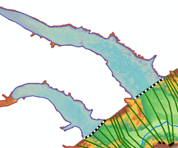
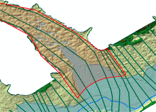
The third option is to extend the normal cross sections up into the tributary, and use ineffective flow areas for that portion of the cross sections. This option is depicted in the figure below. This is the least accurate of these three approaches, and should only be used for very short tributaries in which you are just trying to capture the available storage for which the flood wave could back into. This is not a recommended approach for a tributary of significant size, or in which the tributary would have a sloping water surface elevation. Additionally, when storage is modelled as part of the cross section, it has the same water surface elevation as the cross section, and it is available to put water into instantaneously and take water out of instantaneously.
Modeling Levees and Major Roads. Downstream levees and major roads, that normally prevent water from getting into protected areas, must also be considered. In general it is best to model the area behind the levees separately as a 2D flow area, a storage area, a series of interconnected storage areas, or another routing reach. The details of modeling an area behind a levee will depend on the terrain and details of the interior area. A lateral structure (weir) should be used to model the top of the levees and major roads. Using a lateral structure to model a levee in HEC-RAS allows the model to evaluate levee overtopping, breaching, and the filling of the interior area separate from the main river and floodplain. An example of modeling a levee and protected area with a single storage area is shown in the figure below. 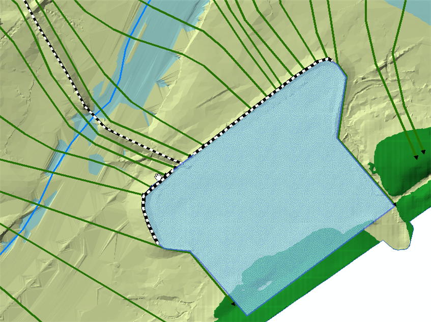
If a levee or road is only a small obstruction to the flow, such that it will be completely overwhelmed during the routing of the dam break flood wave, then it may be better to model that levee/road as part of the general cross sections. This means using cross sections to model both the interior and exterior area around the levee, and using the HEC-RAS cross section levee option to keep flow in the river side of the levee until the levee is overtopped. This should only be done for small levees/roads, in which the area behind these levees is not a significant area/storage volume. An example of this type of modeling is shown in the figure below.
