Download PDF
Download page Step 2: Identify Design and Upstream Reference XSs.
Step 2: Identify Design and Upstream Reference XSs
Choose the River, Reach, and River Station of the design and reference cross sections in the Edit tab above the main riprap calculator.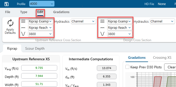
Select the Design Cross Sections
The Design Cross Section should be the cross section that will exert the highest hydraulic forces on the bank. This will be the critical condition for rock mobility, and will determine rock size.
The critical cross section location is generally on the outside and downstream end of a bend.
Note:
The USACE riprap calculation is only based on the reference cross section. It does not use the design cross section anywhere in the calculations. But you still must identify a design cross section to compute the radius of curvature and it is just good design and engineering practice to identify the worst-case design location. The Scour Calculator does use the design cross section in its calculations.
Select the Reference Cross Sections
The USACE Riprap equation is based idealized 1D measurements. A schematic of the ERDC Riprap test facility - used to develop these equations - is included below. The stable rock size in the bends was not correlated to local velocities, or even the average velocity in the bend, but in a straight, symmetrical, idealized reach upstream of the bends.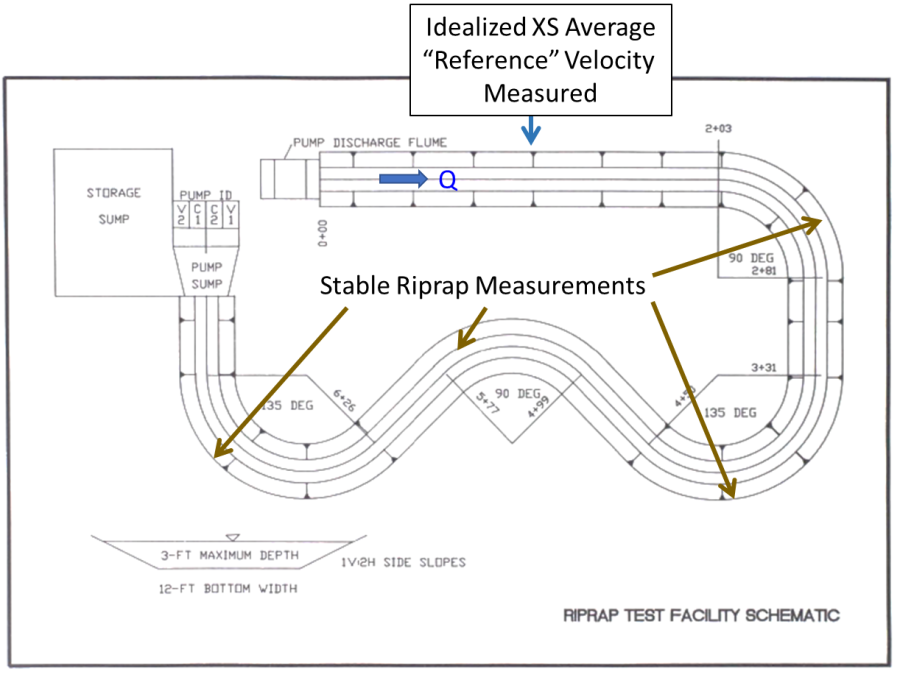
To respect the assumptions of the analysis and transfer these mesoscale laboratory data to field applications, we must not only use 1D cross-section average velocities, but 1D velocities in a relatively symmetrical, idealized reach upstream of the bend.
The figure below identifies an idealized design and reference cross section. The design cross section is highly asymmetrical, with a deep pool on the outside of the bend. This cross section shape is the result of helical flow and multi-dimensional processes. An average XS velocity from this cross section is not appropriate for the empirical equations used in this calculator. The "crossing" or "run" cross section upstream has a more symmetrical geometry. One-dimensional, cross section averaged, velocities at this cross section are a better approximation of system velocities and the analysis assumptions.
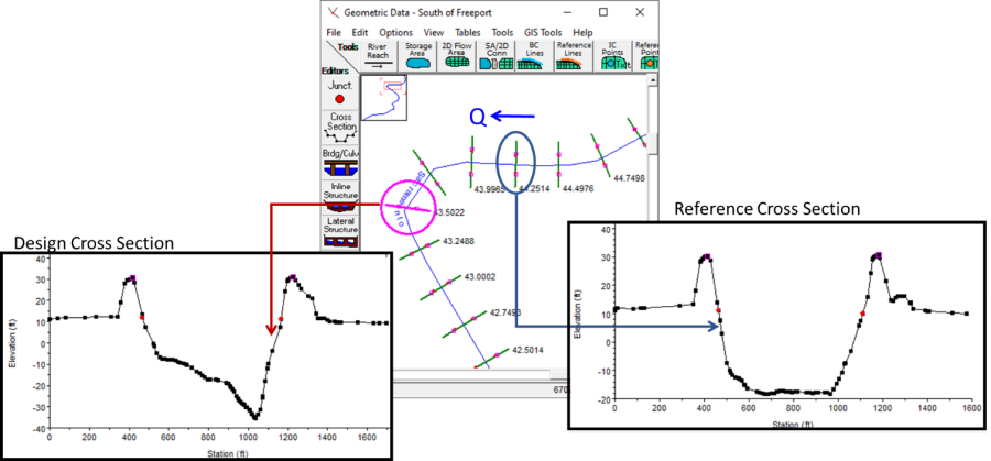
The next figure shows the selected design ("evaluation") and reference cross sections for an actual USACE study on the American River (Howard et al., 2021). 
Hydraulic Averaging Assumption
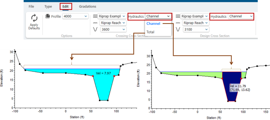
HEC-RAS can provide two average velocities for the Design and Reference Cross Sections. The model can average velocity over the entire cross section (including channel and flood plains/overbanks) or it can report an average velocity for the channel alone (the region of the model between the bank stations ![]() ).
).
Modeling Note:
It is important that bank stations are defined appropriately for the riprap design flow. Bank stations that have been set based on the low-flow channel may need to be revised to reflect the effective main channel for the design condition.
The riprap experiments used the entire cross section, but only used idealized, trapezoidal channels. They did not consider or measure results from compound channels. Therefore, qualitative engineering judgement is often required to apply these results to natural, compound channels. The channel velocity will usually be more appropriate for this analysis and is the default.
Results will be sensitive to the reference cross section selected, so Sensitivity Analysis are recommended (see section on the persistent d30 tool).
The Riprap and Scour Calculator use the same design and reference cross section. These are global options that affect both tabs.
Summary of Hydraulic Modeling Considerations for Riprap Analysis
- The typical USACE project design approach is to select the critical velocity / stone size from the reference and design cross sections for an entire reach and use that for rock size, gradation, and construction plans. Most USACE projects will use only one or two riprap gradations for the entire project to be economical from the quarry and for constructability
- The user often will create a geometry with modified parameters (ineffective flow, roughness, expansion / contraction coefficients) to compute the best estimate velocity for use with the calculator.
- Converting unsteady flow models to steady flow for application with the Riprap calculator will often require revised model calibration.
- Run a full range of frequency profiles to select the most critical design condition with informed user choices for risk tolerance.