The riprap and scour calculator will plot selected results with the design cross section to help visualize the magnitude and range of computed scour.

Visualizing General Scour

The general scour results plot automatically, reproducing the portion of the cross section between the channel banks, offset vertically by the scour result.

Visualizing Bend Scour

Visualizing bend scour requires user input. Bend scour is not distributed across the whole channel, but is generally concentrated at the toe of one bank. So the Riprap and Scour calculator requires a Toe Station to display the bend scour results correctly.

In the following figure, the Toe Station is 165. The display includes an orange, dotted, line to indicate the location of this user-defined Toe Station. The cross section has no station-elevation point right at station 165, so it selects the closest point (which is at the left toe of the engineered, trapezoidal channel).The bend scour visualization applies the computed scour depths to the selected station-elevation point, and connects them to the adjacent station-elevation points.

Note:

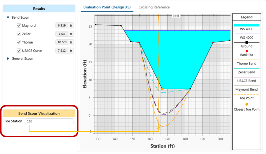
The bend scour visualization is dependent on the number and location of station elevation points. For example, the bend scour visualization above would look very different if the modeler used more station-elevation points to define the cross section.

These figures plot the same bend scour results on the same cross section. The only difference is the cross section on the right has more station-elevation points. The additional station elevation points do not affect the result but change the visualization substantially.