This section discusses the navigation dam option in HEC-RAS. For a navigation dam, the program will try to maintain both a minimum and maximum water surface at one or more locations along a navigation channel. The program does this by controlling the gate settings on an inline structure. The user enters a target water surface (and various other calibration data) and the program will adjust the gate settings at user specified time intervals in order to meet the target water surface as closely as possible. This section describes the data requirements for a navigation dam and includes a general discussion of how the gate operations are performed.
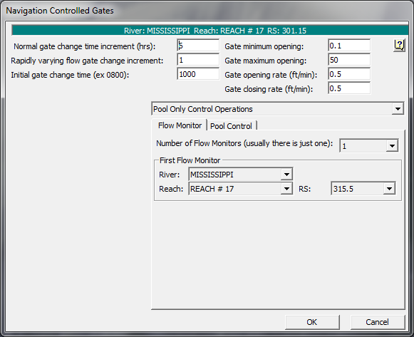
The first step in modeling a navigation dam is to add the physical data for the navigation dam by selecting the Inline Structure option on the Geometry Data editor and entering the appropriate information. The next step is to add the inline structure as a boundary condition on the Unsteady Flow editor and then click the Navigation Dams button. The editor, as shown in Figure 14-30, will appear (note: the fields will be blank when the editor first appears).

Figure 14‑30. Navigation Dam Editor with Flow Monitor
Normal gate change time increment – This field states how often the program will adjust the gate settings. In the example shown in Figure 14-30, the program will only make adjustments to the gates every six hours under normal operations.
Rapidly varying flow change increment – This field represents the minimum length of time between gate setting adjustments. For example, during rapidly changing conditions, the program can adjust the gates up to once an hour in order to maintain the appropriate water surfaces.
Initial gate change time – This field is the time (military style) for when the first gate change will take place. In this example, it is 10:00am. If the simulation starts after 10:00am then the gates will be first adjusted at 4:00pm, 10:00pm, or 4:00am as appropriate.
Gate minimum opening – This field is the minimum opening for the first gate group (the first gate group as defined on the Geometry editor). The program will keep the gates on this gate group open to at least 0.1 feet. The other gate groups may be closed completely (see discussion of gate opening and closing below).
Gate maximum opening – This field is the maximum opening for the first gate group (the first gate group as defined on the Geometry editor). The program will not allow the gates on this gate group to open more than the specified value. If this field is left blank, then the default is the physical gate maximum opening from the geometric data.
The final two fields [Gate opening and Gate closing rate] are the maximum speed that the gates in any gate group can be opened or closed. Generally this rate is determined by the physical speed with which the gates can be adjusted. Sometimes, however, opening or closing the gates too quickly can cause instability in the unsteady solver. In this case, it may be necessary to reduce the opening or closing rate. A shorter time step may also help.