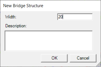
The Bridges/Culverts layer is used to locate the centerline of road crossings. The bridge should be created from left to right when looking downstream, crossing the river line exactly once. When a new bridge is created a dialog will be prompt the user to enter the Width (in the direction of flow) for the structure and provide a Description, if desired. The bridge's River Station is computed based on the intersection with the River layer (just like the cross sections).
Information for the Deck/Roadway Data Editor is extracted from the proximity of the Bridge structure to surrounding cross sections for the Distance property, while elevation information is extracted from the Terrain layer.
Bridges/Culverts information will need to be completed in the Bridge/Culvert Data Editor.
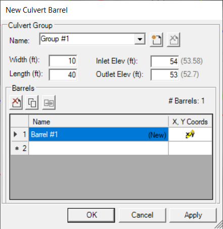
Culvert Barrel Editor
Culvert locations can then be specified by selecting the Culvert Barrels layer and drawing from the upstream to downstream where the culvert is located. When finished, the user can provide information for the Barrel Name and Culvert Group information for barrel Width, Length, Inlet Elevation, and Outlet Elevation (the Terrain elevations corresponding to the inlet and outlet will be shown next to the user-specified elevations). For each each additional culvert, the Culvert Barrel Editor will default to the last Culvert Group specified.
Plotting Bridges
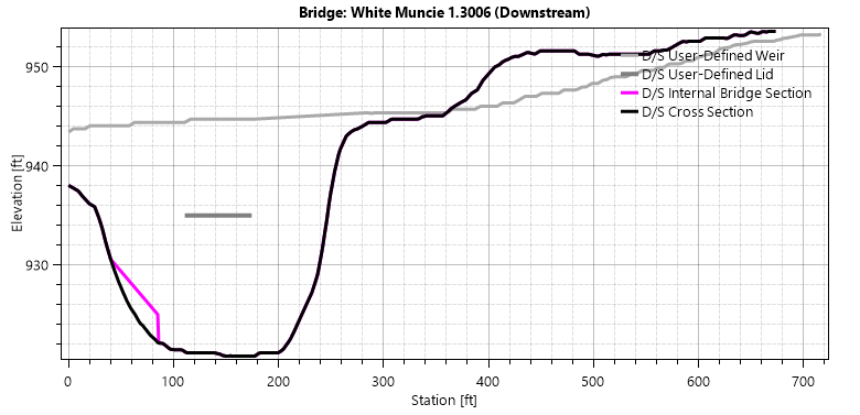
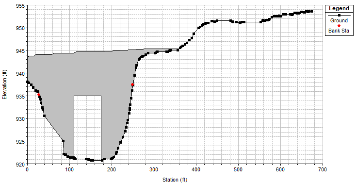
Plotting structures is available by right-click on the structure of interest. You can always plot the Terrain Elevations for any line in RAS Mapper. Plotting the Bridge itself, has a limited capability in RAS Mapper. Once information has been entered for a bridge in the Bridge Editor, a the bridge may look like that shown below which is a complicated plot that creates a composite weir from deck information and the ground elevations of the bounding cross sections.
In RAS Mapper, the Plot Bridge Data will result in a plot for the upstream and downstream sections of the bridge. Bridge information that has been defined by the user will be plotted along with the cross section bounding the bridge. The bridge plot will show the user-defined Weir, Lid, and Internal Bridge Section along with the bounding Cross Section.