Download PDF
Download page HOW TO Convert a ResSim Watershed to a New Projection.
HOW TO Convert a ResSim Watershed to a New Projection
HOW TO…
Convert a ResSim Watershed into a New Projection
You might be asking… why would you even want to do this? Well, a number of reasons come to mind but the most common reason is because the ResSim model needs to be used in concert with a few other models that have been built in a different projection or coordinate system.
Regardless of the reason, there is no easy way to do this. ResSim does not have a magic button that says "convert coordinate system". However, don't assume you have to rebuild the ResSim model from scratch, piece by piece, either – although it is going to seem like it when you read through the first part of the instructions below. But we've assembled these instructions in the hope that you can get through the process with the least fuss and bother possible.
General Overview
The basics – yes, you are going to create a new watershed. This new watershed will have a new set of background maps and a new stream alignment. You will recreate the computation points and the projects – all the stuff that makes up your watershed configuration(s).
This is the point at which you should meet with your watershed modeling team to revisit the extents of the watershed and the selection and naming of the elements to be represented in it. For example, your original model may have used a naming convention that you may now want to change – this is your chance. Or, perhaps you need to combine two or more existing watersheds into one larger watershed – this is the time to make that decision and create the stream alignment and the configuration(s) accordingly.
After re-creating the stream alignment, configuration(s) and the computation points, then you will create a new network based on your new configuration (at least one network per configuration) and use ResSim's import element properties feature to fill in it in. In the details below are some clues for what to look for that will need to be corrected, completed, or recreated.
Once your new network is complete, you will need to create a new alternative and set it up to match your original alternative. Once your alternative is complete, you will create a ResSim simulation to verify that the alternative and network are complete and compute properly. You should also compare results from your new alternative to results generated by your original alternative in the original watershed.
Detailed Instructions
Since you are working with an existing watershed, these instructions assume that you know how to use ResSim to perform the steps described. However, since that isn't going to be true for everyone, some hints have been included in brackets [] to point you in the right direction.
Export your stream alignment to a shapefile. [Watershed Setup module, Watershed menu, Export, Stream Alignment…]. Note, if your stream alignment was originally imported from a shapefile, you may not need to perform this step if that shapefile is still one of your background maps
Export the computation points to a shapefile, too. [Watershed Setup module, Watershed menu, Export, Configuration Elements…] Note, even if your computation points were originally imported from a shape file, it is very likely that the set of computation points in your model were modified after importing, so it will be easiest to just export them to a new shapefile.
- Give the original background maps from your to your GIS folks along with the stream alignment and computation point shapefiles you just created. They have software, such as ARC-GIS, that they can use to re-project your maps and shapefiles to the new coordinates system and units. YES, I added units, because sometimes, the principal reason for doing all this is because the original maps (while possibly already in the desired projection) were unfortunately saved using METERS. And because you are probably integrating the ResSim model with an HEC-RAS model in FEET, the maps need to be converted to FEET units (or vice versa).
Once you have the reprojected set of background maps and stream alignment and computation point shapefiles, create a new watershed in ResSim and copy the maps and shapefile to the maps folder. Add each new maps to your watershed as well as the stream alignment and computation point shapefiles. [View menu, Layers…, etc.]
Import the stream alignment from the new shapefile [Watershed Setup module, Watershed menu, Import…, Stream Alignment].
- DON'T think you are done with the stream alignment just because the import seemed to work ok. You should:
- Verify that the streams are flowing in the right direction. To do this, make sure that the stream stationing starts at zero at the downstream end of each stream and increases as you move upstream. If you find that the stationing starts at zero at the upstream end and increases as you move downstream, right-click on the stream with the stream alignment tool and select "reverse direction". You need to verify (and fix as needed) each stream in your stream alignment.
- Verify that all streams that connect at a confluence are actually connected. Check to be sure that there is a bright green halo around the dark green dot at the confluence.
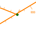 No bright green halo (as shown at left) means no connectivity. To correct the connectivity, zoom in to the confluence, then using the stream alignment tool, double-click on the tributary reach. The reach should turn yellow and all the vertices of the line will get blue dots. "grab" the downstream-most dot and drag it onto the "Mainstem" stream where you want the confluence to be formed. You will be asked "Ok to connect stream Tributary to stream Mainstem?"
 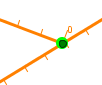 When you click OK, you should see a bright green halo appear around the dark green dot at your new confluence.Remember, there may be confluences where one stream becomes another – this may not look like a confluence but it really is – at least to the stream alignment logic, so don't forget to check those out, too.
- If needed, revise the stream stationing. In stream alignment terminology, the dark green dots are called stream nodes and a confluence is called a stream junction. By default, there are at least two stream nodes per stream – one at each end. An additional stream node is added to the stream at each stream junction. The purpose of the stream nodes is to establish the "stationing" along the stream. By default, the stationing is in the "length" units of the watershed maps. If the maps are in feet, then the default stationing represents the length or distance in feet (from zero at the mouth) along the stream. IF you feel you need to perform this step, it is usually because you want the stream stationing to represent river miles instead of feet. You can accomplish the re-stationing of a stream by editing each stream node, unchecking the box "use default stationing" and entering a new value in the station field. Use the stream node tool to access the editor for stream nodes and stream junctions. You can also use the stream node tool to add additional stream nodes if you need to specify the known river mile of key locations, such as gages or landmarks.
- After your stream alignment is complete, save the watershed so that your changes are save to disc.
- Add the reservoirs, diversions, levees, and computation points.
The computation points should be imported from the computation point shapefile [Watershed Setup module, Watershed menu, Import…, Computation Points]. After the import, review the schematic carefully to be sure that the computation points really are attached to the streams of your stream alignment. The brute force way to do this is:
Open the Computation Point Editor by right-clicking on a computation point in your schematic and selecting Edit from the context menu. From this editor, you can edit any computation point in your watershed by selecting it from the name dropdown list or using the arrow buttons. For each computation point, verify that there is a valid stream name in the stream name field. If the stream name is empty, check the "Snap to Stream" checkbox and click Apply. If the stream name field is not empty, uncheck then recheck the "Snap to Stream" checkbox and click Apply.
- If you do not have a shapefile containing the computation points, you will need to draw them in by hand using the computation point tool. This is usually a good method of adding the computation points but you should still verify that the points are "connected" to the stream by double-clicking on the computation point so that you get the "move" handles then dragging the point along the stream alignment. Perform this verification as you add each point. By making this verification a part of your process, you will reduce the effort involved and head off possible problems later.
- Create a watersehd configuration next. If you are going to represent multiple subwatersheds within a larger one, then be sure to create a configuration for each subwatershed.
- Now, add the reservoirs, diversions, and levees. Make the main, all inclusive, configuration the active configuration, then using the relevant project tool, place your projects into your schematic and give each an appropriate name, per your naming convention. After adding all the projects to the watershed, open the configuration editor to verify the project list for each configuration and adjust as needed.
- Review the watershed setup carefully to verify that you have included all the needed projects and computation points. No matter how many times I do this, I often find later that I've missed a few computation points (often at confluences). It would be nice if you had the configuration(s) finished at this point but know that you may iterate back here a few times before you are done.
- Save the watershed.
9. Change module to the Reservoir Network module. Create a new network, based on one of the configurations you specified above. All the computation points plus those projects included in the selected configuration will become model elements in your new network.
10. If your selected configuration represents only a sub-watershed of the larger watershed, you may now have junctions you don't want based on computation points outside the sub-watershed. You can delete extra junctions one by one from the schematic or you can use the Junction List from the Reports menu to select several at once to delete. When using the Junction List, each time you select a junction in the list, it will highlight on the schematic, so keep the list to the side of the schematic so that you can see the highlighted junctions. You don't want to accidentally delete a junction that you intended to keep or you will have to start all over with the delete process (after "updating the network from the configuration" or creating another new network).
11. Add routing reaches. The reaches should complete the connectivity of your network. Other elements that may be added include diversions and diverted outlets that you may have chosen to not include in the configuration. You may also find you need additional junctions to break up routing reaches that change parameters along their distance. If the additional junction is just for this purpose, to allow you to define the routing more effectively, then the new junction is probably ok to be added only at the network level. However, if the new junction is needed at a confluence or at a location where an incremental local flow will be brought in, then this really should have been defined as a computation point in Watershed Setup. Go back to the Watershed Setup module, add the computation point, save the watershed, then return to the Reservoir Network module, update the network from the configuration, and return to step 10 if necessary.
12. Save the network. When you have finished adding the routing reaches and other connectivity elements to the network, save it. You may need to return to this state later.
13. Next, import the element properties from your original network into this new network. This step can be challenging, especially the first few times you do it. Remember, you saved the network before you started the import, so it is ok if you need to exit the importer before completing the process to go back and correct something (like a missing routing reach). It is also OK to proceed all the way through the import and then decide that you want to do it again and make different decisions or selections the next time. The import of the properties of an element will replace whatever is already there; imported data will not be "added to" previous info. Or, you can reopen the saved network, thus throwing away your import and starting over with a clean slate.
Importing can be done in stages. You can import into a few elements at a time or you can try to import into all elements of your network at once. I have found that importing reservoir properties is the hardest part, so depending on the size or complexity of the network I'm importing to or from, I often choose to import the reaches and junctions first, then I restart the Importer and import the reservoirs, sometimes only one or just a few at a time rather than all at once.
The challenge with importing the reservoirs (and diversions) is the step in the import where you must "resolve the Network Connectivity". This is the step where you need to help the Importer identify the elements or model variables that a rule, zone, or if-block expression that is being imported is supposed to reference.
If the connectivity you are trying to correct/specify is for a downstream control rule and the location it needs is not being provided by the Importer in the selection list – then either leave it blank and make a note of the rule name and missing location so you can recreate the rule by hand later, or stop the import process and find out why the Importer cannot provide the needed location in the selection list – usually it is missing for one of three reasons:
- the location was not created in this new watershed
- the location now has a new name that you didn't associate with the original name
- or your network connectivity is broken or incomplete making it impossible for the importer to look down the river system to the location of interest.
If the connectivity you are trying to correct/specify is for a model variable or state variable that is not included in the selection list, don't worry – you do not need to stop the Importer. The Importer currently does not provide a very expansive list of model variables to select from. But, don't let this stop you. Make a note of the name of the element, its rule/zone/etc , and the model variable it wanted, then select a model variable from the available list so that the rule is imported "properly". After the import, edit the reservoir, find the rule/zone/etc in the Operations tab of the Reservoir (or Diversion) Editor and reset the model variable to what it had been originally.
14. The import process is pretty good and saves a lot of time in data re-entry – but nothing is perfect so you will need to review the imported data carefully to be sure it has imported correctly. In addition to the rules/zones/etc that are a function of a model or state variable (as described above), the importer has problems identifying the model or state variables referenced in the conditional expressions of IF-Blocks. For each reservoir and each of its operation sets, find and correct any variable references that have not imported correctly. Incorrect references usually begin with the identifier "~E".
HINT – At this point, it may be helpful to launch a second instance of ResSim and open the original watershed and network. Use it to help with verifying the rules and IF-Blocks in your new network. |
In addition to correcting references in the if-block conditional expressions, carefully review all rules and zones in each operation set as well as any additional specifications such as release allocation. Although most rules and zones import without issue, don't assume everything is ok until you check. Also, don't forget the rules and if blocks that may not be used in any operation set. They are hiding in the "Use Existing.." lists. To inspect these, create a temporary operation set (or zone in one of your current operation set) and add them all to it, then correct them as needed or delete them from the reservoir if they are no longer needed or cannot be corrected. After reviewing all remaining "unused" rules, you can delete the temporary operation set or zone. Save the network.
Unfortunately, your network review does not stop with the reservoirs and their rules, zones, and if blocks. Other features to check out include Diversions, State Variables, and Reservoir Systems. Like reservoirs, diversions "operate" to a diversion rule which can be function of a model, state, or external variable; as such, the "connectivity" to the right variable could be incomplete or wrong as a result of the import. Be sure to check each diversion carefully. Also, although state variables usually import without issue, I have seen problems occur due to repeated imports of the associated reservoir or diversion. So, check your state variables carefully. And one more thing, although the script of a state variable or scripted rule may have imported perfectly, if model elements that it references have new names in the new network, the importer is not going to correct those references for you – you are going to have to do that. Save the network.
15. If possible, recreate one of the alternatives that used the network you just recreated. You will usually want to recreate all the alternatives from the original watershed in the new one, but not always. For now, just recreate one. The idea is to use this alternative to validate the new network. Since ResSim cannot import alternatives, you will need to create a new alternative in the Alternative Editor, select the new network you just created.
HINT – that second instance of ResSim becomes useful again. In the second instance, open the alternative editor to the alternative in the original watershed that you are trying to recreate. |
Now, tab by tab, set the new alternative's settings to those of the original. Realize that most of the tables of data, like lookback settings and time series are not likely to be in the same order in the new network as they were in the old, but it is still possible to copy and paste data from one to the other (using Ctrl- C & Ctrl V), just do it carefully.
Don't forget to copy the source DSS files used in your alternative into the new watershed. I recommend using the shared folder of your watershed to store dss files, but you could also add a data folder and put them there if you prefer. Be sure that each time series correctly references its source DSS file in your new watershed.
It is possible that the network you are working on is completely new, perhaps a combination of data from one or more networks that modeled sub-watersheds of the watershed model you are now working on. In this case, your original watershed may not have an alternative you can directly duplicate, however, there may be alternatives that have a lot of information that you can use to create the alternative(s) you will need in your new watershed for your new network. Use the suggestions above as appropriate to help you create your new alternative.
16.
Create a simulation and test your new alternative. If you duplicated an alternative from the original watershed, create a simulation for the same time window as was used with the associated alternative and add your new alternative to your new simulation. Compute it. If it doesn't compute successfully the first time, take heart, that's fairly normal. There are a number of small things that can occur during this "rebuild" process that can sneak in on you. Address each error you encounter until it computes. [Note – you might also double check that the alternative you "duplicated" actually ran in the original watershed. More than once, I've worked my way through error after error only to discover that the network and alternative I was duplicating had never successfully computed in the original watershed.]
Errors to look for:
- Missing Lookback settings – more often than not, at least one outlet did not get its lookback setting established. If you, like me, typically set the total lookback release to one of the reservoir's outlets, then the others should all be set to constant with a value of zero – a constant value of "blank" will cause an error.
- Missing Diversion definition – the ResSim Diversion Editor can trick you by showing you a diversion with its method set to constant with a value of zero. This is what the editor shows by default, but those settings are not saved unless you enter them yourself. Just enter a non-zero value into the constant field, then delete it and type in zero – if that's what you want – then click OK or Apply.
- Invalid time window – if you give your simulation a time window for which you do not have data, your simulation won't compute due to "Missing Data". You can edit the simulation to revise the end points (lookback and end times) of the simulation time window, but you cannot change the simulation time. If you need a completely new time window, you'll need a new simulation.
- "Ghost nodes" – these are characterized by the message: "Input time series not found for Node nn" where nn is a number. I refer to these problematic nodes as ghosts because they get left behind when something (usually a reach) is deleted or when something was started but not quite finished being created. Ghost nodes can be found and deleted from the Node List in the Network module:
- Switch to the Reservoir Network module
- Open your network (if it isn't already open)
- From the Reports menu, open the Node List from the Advanced submenu.
- Sort the list by Name (by clicking on the Name column header).
- Scroll down to the Ns. Find and select any and all nodes with a name starting with "Node".
- From the Edit menu of the Node List, select Delete Node.
- Close the Node List.
- Save the network.
- Return to the Simulation module, right-click on your alternative in the Simulation Control panel at the right and select Replace from Base from the context menu.