Download PDF
Download page Reservoir Outflow.
Reservoir Outflow
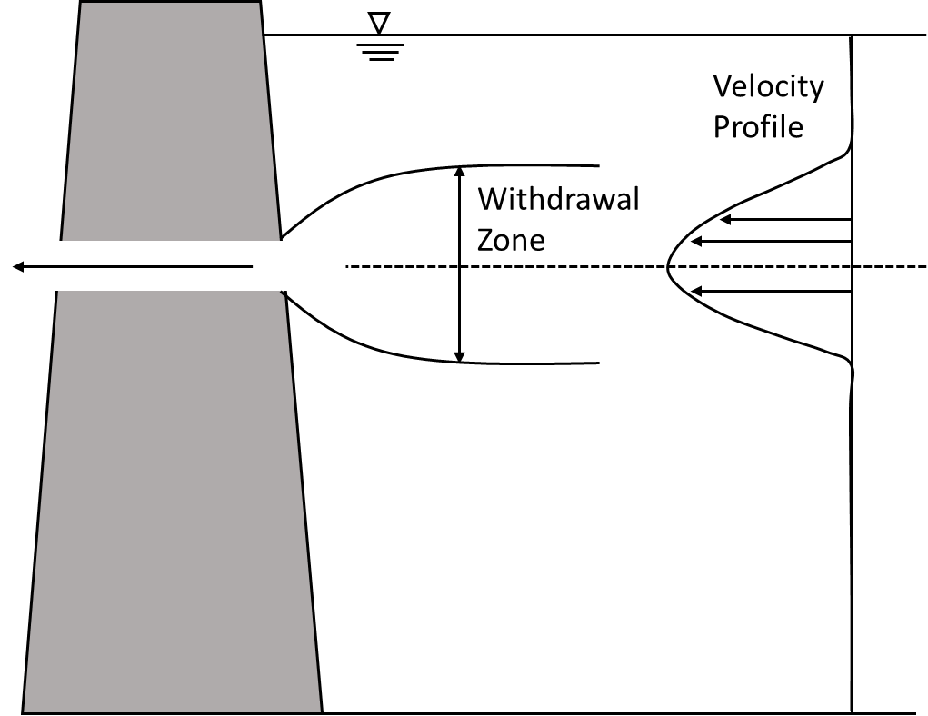
When water leaves a reservoir through an outlet on the dam, it pulls from a range of elevations about the outlet centerline (the withdrawal zone). The figure below (redrawn from Davis et al., 1987) illustrates a typical withdrawal zone and the accompanying velocity profile.
The thickness of the withdrawal zone is determined by:
- the magnitude of the outflow (higher outflows create a thicker zone),
- the current state of stratification near the outlet (greater stratification limits vertical movement and creates a thinner zone), and
- the presence of interfering boundaries such as the water surface or the reservoir bottom.
In ResSim, the total outflow for a outlet must be apportioned to the individual layers in the reservoir; this is done following the algorithms of the USACE SELECT Model (Davis et al., 1987). The equations of the SELECT Model have been verified over a number of laboratory and field experiments, and have been utilized by several reservoir water quality models, including CE-QUAL-R1 (Environmental Laboratory, 1995), CE-QUAL-W2 (Cole and Buchak, 1995) and HEC-5Q (HEC, 1986). A brief description of the methodology is given below. Although the equations are semi-empirical, the forms below do not rely on input data in a specific unit system; SI or English units can be used, as long as the unit system is consistent.
Determination of Withdrawal Zone Interference
The upper and lower boundaries of the withdrawal zone are first calculated to determine if there is interference by the water surface or reservoir bottom. If interference exists, it will influence the shape of the velocity profile. This determination is made using the equation:
| 1) | \frac{Q}{Z^3 N} = \frac{\theta}{\pi} |
where
Q is the outflow rate,
Z is the distance between the upper or lower withdrawal boundary and the outlet centerline, and
\theta is the withdrawal angle in radians (\pi for withdrawals near the dam wall).
N is the buoyancy frequency, which describes the strength of stratification. In this context, it is defined as:
| N = \sqrt{\frac{\Delta\rho}{\rho}\frac{g}{Z}} |
where
\Delta\rho is the absolute value of the density difference between water at the outlet centerline and water at the upper or lower withdrawal zone boundary, and
\rho is the density of water at the outlet centerline.
Interference is determined by rearranging 1) to obtain:
| 2) | Q - \frac{Z^3N\theta}{\pi}=0 |
and substituting the distance from the outlet to the physical boundary for Z and the density difference between the outlet layer and the surface or bottom layer for \Delta \rho. If the left-hand side of 2) is positive, then interference exists.
Free Withdrawal Zone
If the evaluation of the left-hand side of 2) is negative for both upper and lower boundaries, then the withdrawal zone forms freely. Equation 1) is solved iteratively to determine the upper and lower limits of the withdrawal zone. Following that, the distance from the lower boundary to the elevation of maximum velocity (Y_L) is calculated using:
| 3) | Y_L = H \, \textrm{sin}^2\left(\frac{\pi}{2} \frac{Z_L}{H}\right) |
where
H is the total thickness of the withdrawal zone, and
Z_L is the distance from the lower boundary elevation to the outlet centerline.
The elevation of maximum velocity is often located above the outlet centerline, because of the shape of a typical stratification profile. A normalized, parabolic velocity profile is then calculated for each reservoir layer within the withdrawal envelope
| 4) | v^{\textrm{norm}}_i = \left(1 - \frac{y_i}{Y} \frac{\Delta\rho_i}{\Delta\rho_{\textrm{max}}}\right)^2 |
where
v^{\textrm{norm}}_i is the normalized outflow velocity for layer i,
y_i is the distance between the elevation of maximum velocity and the elevation of the centerline of layer i,
Y is the distance between the elevation of maximum velocity and the upper or lower withdrawal boundary,
\Delta\rho_i is the absolute value of the density difference between the layer containing the maximum velocity elevation and layer i, and
\Delta\rho_{\textrm{max}} is the absolute value of the density difference between the layer containing the maximum velocity elevation and the layer containing the upper or lower withdrawal boundary.
The figure below (redrawn from Davis et al., 1987) illustrates some of these definitions.

Finally, withdrawal flows at each layer (Q_i) are calculated as:
| Q_i = \frac{v^{\textrm{norm}}_i}{\sum_i v^{\textrm{norm}}_i}Q |
where Q is the total inflow.
Withdrawal Zone with Interference
If interference at the surface or bottom exists, the distance from the outlet to the opposite, freely-forming withdrawal limit is calculated using a modified version of Equation 1):
| \frac{Q}{D'^{3}N} = \frac{0.125\phi}{X^3} \frac{\theta}{\pi} |
where D' is the distance to the outlet and the following variables have been defined to simplify the writing of the equation:
| \phi = \frac{1}{2} \left[1+\frac{1}{\pi} \textrm{sin}\left( \xi \pi\right) + \xi \right] \newline X = \frac{1}{2}\left(1 + \xi \right) \newline \xi = \frac{b/D'}{1-b/D'} |
b is the distance between the centerline and the interfering boundary, and the buoyancy frequency term is defined as:
| N = \sqrt{\frac{\Delta\rho}{\rho} \frac{g}{D'}} |

A theoretical withdrawal boundary, located outside of the reservoir elevation limits, can be calculated for the boundary experiencing interference using Equation 1). In this case, \Delta\rho is extrapolated outside of the reservoir limits using linear interpolation. The calculation of the maximum velocity elevation is the same as given in Equation 3), and the normalized velocities for the half of the outflow experiencing interference are calculated a modified version of Equation 4).
| v^{\textrm{norm}}_i = 1 - \left(\frac{y_i}{Y} \frac{\Delta\rho_i}{\Delta\rho_{\textrm{max}}}\right)^2 |
For the case where both upper and lower boundaries experience interference, theoretical withdrawal limits are calculated for both.
Outflows Under Isothermal and Near Isothermal Conditions
When a reservoir nears isothermal conditions, Equation 1) suggests that the thickness of the withdrawal zone becomes very large. The computed velocity distribution is nearly constant with depth, and the outflow is pulled from all reservoir layers equally. For large reservoirs, where the outlet may be located hundreds of feet from the reservoir surface or bottom, this result is unrealistic. In order to provide a more representative withdrawal envelope under these conditions, a user-defined parameter was introduced to limit the withdrawal envelope. This limits the total thickness of the envelope to some maximum value.