Download PDF
Download page The Junction Editor.
The Junction Editor
Use the Junction Editor ("Figure: Junction Editor - Info Tab") specify the properties of the junctions in your network.
The Junction Editor has four tabs on which you will define your junction data:
- Info
- Local Flow
- Rating Curve, and
- Observed Data.
These tabs are described in the following sections.
Info Tab
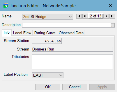
Figure: Junction Editor - Info Tab
The Info tab of the Junction Editor ("Figure: Junction Editor - Info Tab") displays the Stream Station, Stream, and Tributaries associated with your junction. These properties describe the junction's relationship to the stream alignment.
Stream Station—the position of the junction is described as its distance (in map units) from the downstream end of the stream it's on in the stream alignment.
If the junction is not associated with a computation point in a watershed configuration, the Stream Station can be edited. However, by changing the stream station of a junction, you are changing the position of the junction along the stream alignment, so be careful with this option, you can get unintended consequences and there are restrictions — for example, you should not attempt to move a junction above or below another junction on the current stream by changing its stationing.
The Stream and Tributaries fields are provided so that you can verify that the junction is located where you intended when you placed it in your schematic from the Reservoir Network or Watershed Setup module.
Label Position
Near the bottom of the Info tab is a Label Position field. This field is a dropdown list that contains the 8 points on the compass (North, South, East, West, Northeast, Northwest, Southeast, and Southwest). Use this field to control where the label for the current junction will display in the Map Display area. The junction's Name will be drawn horizontally in the position you selected with respect to the center of the junction (plus a small offset).
Local Flow Tab
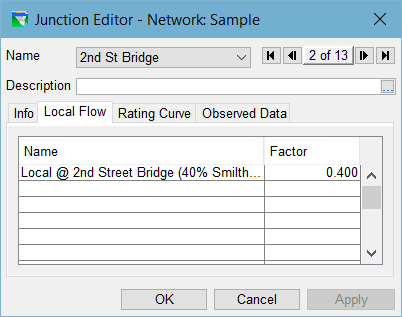
Figure: Junction Editor - Local Flow Tab
The Local Flow tab ("Figure: Junction Editor - Local Flow Tab") of the Junction Editor contains a table where you can identify one or more inflows entering the river system at this junction.
You must identify at least one inflow at each headwater junction in your watershed; inflows at all other junctions are optional. Each inflow is identified by a unique Name and Factor.
Name — The name of each Local Flow should identify the source of the inflow or contain some other uniquely identifying information so that it will be clear what is required when it comes time to associate a time series of flow data with this inflow in the Time-Series tab of the Alternative Editor. (See "Alternative Editor" for more on creating Alternatives.)
NOTE: Local flows cannot have the same name as a junction (or any other network element.
There is limit on length of the local flow name, but it should be unique within the first 24-32 characters. And, since this name will be used in the B Part of a DSS pathname, do not use the following characters: \ ' / ` " and |.
Factor: The factor value is provided to enable you to provide a weighting of the values in the associated inflow hydrograph. Use this Factor for "basin weighting" of a single inflow hydrograph across multiple junctions. The default value for the Factor is 1.0.
When you identify one or more local inflows on the Local Flow tab of a junction, then a visual clue will appear in your model schematic in the map display. This visual clue appears as a white circle or halo around the junction, as illustrated in "Figure: Junction with Local Inflow". The white halo makes it easy to tell at a glance where inflows are coming into your reservoir network.

Figure: Junction with Local Inflow
Rating Curve Tab
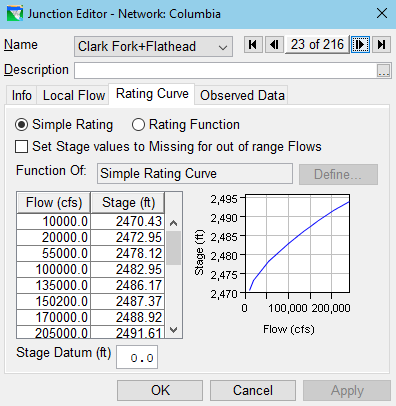
Most junctions do not require a rating curve, but for those that do or for any junction where you would like ResSim to output stage associated with is computed junction flow, you can use the Rating Curve tab ("Figure: Junction Editor - Rating Curve Tab") to enter a rating curve for that junction. Two options are available for entry of a rating curve — Simple Rating and Rating Function.
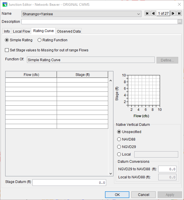
Figure: Junction Editor - Rating Curve Tab
Simple Rating — A Simple Rating can be used where you have a relationship between Flow and Stage at the junction. ResSim considers Flow to be the independent variable and Stage to be the dependent variable of a rating curve so be sure to enter Flow in the first column of the table and Stage in the second column. "Figure: Junction Editor - Rating Curve Tab" shows an example of a Simple Rating.
Rating Function — A Rating Function can be used when Stage is a function of a variable other than Flow at the junction or when Stage is influenced by backwater effects. If you select the Rating Function option, you will be able to specify a stage lookup table as a function of:
- Model Variable,
- External Variable,
- State Variable, or
Two Variables (such as flow and downstream pool elevation). "Figure: Junction Editor - Rating Curve - Function of Two Variables" illustrates an example of a family of rating curves (stage as a function of two independent variables). For more information on setting the independent variable(s) of a function (lookup table), refer to "Commonly Used Editors and Dialogs".
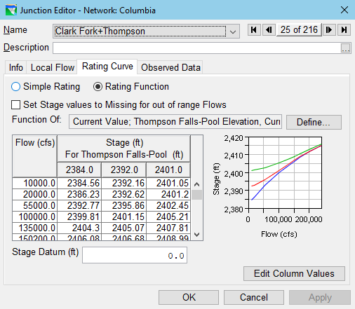
Figure: Junction Editor - Rating Curve - Function of Two Variables