Download PDF
Download page Specifying Release Allocation.
Specifying Release Allocation
UPDATED IN RESSIM 3.5 As of ResSim 3.5, Release Allocation is now defined by sets, like operations. BUG IN RESSIM 3.5There are some bugs that were introduced when making this update - they relate to interaction with the UI.
As we'll see in the next chapter when we create rules, rules can be specified to apply to a specific outlet, thus imposing an "allocation" of the release determined for that rule to the identified outlet. Although rule-based allocation takes precedence, there are usually releases that are not specifically allocated by the rules; these are typically the releases made due to rules or operations that are applied to the dam or reservoir as a whole and are the ones the Release Allocation feature is intended to manage.
Release Allocation is the method ResSim uses to allocate the release from the reservoir to its outlet groups and their available outlets. The Release Allocation feature is available on the Rel. Alloc sub-tab of the Reservoir Editor's Operations tab. This feature enables you to specify the release allocation method by weighting or prioritizing the outlets in your reservoir's outlet hierarchy.
Release allocation logic only applies when releases from a given outlet or outlet group are not constrained, either by a rule in the rule tree or by physical maximum capacity of the outlet.
Three Release Allocation methods are currently available in ResSim:
- Balanced — releases distributed based on default or user-defined weights,
- Sequential — releases distributed sequentially to outlets prioritized by ranking, and
- Stepped — combines the balanced and sequential approaches.
By default, HEC-ResSim uses an evenly balanced (or weighted) allocation scheme to share the unallocated release across the available (see "Capacity Outage Schedules") outlets of a reservoir. The default Balanced allocation scheme is illustrated in "Figure: Release Allocation Editor - Default Allocation - Balanced" below.
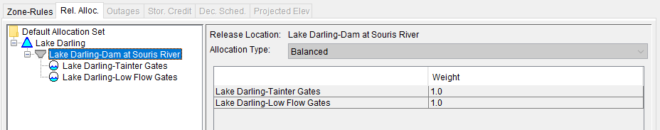
Figure: Release Allocation Editor - Default Allocation - Balanced
However, this default allocation scheme may not be desirable or appropriate for one or more of your reservoirs. For example, in many hydropower reservoirs, all releases are directed to the power plant first (to achieve incidental power generation); other outlets would be used only when the power plant has reached capacity (or when the desired release is too small to send through the power plant efficiently). For this example, a sequential or prioritized scheme for allocating the release should be used.
To edit the reservoir's Release Allocation scheme for the active Operation Set: (Set-based Release Allocation is NEW IN RESSIM 3.5)
Select the Release Allocation sub-tab ("Figure: Release Allocation Editor - Balanced Allocation - Even Balance Example") of the Reservoir Editor's Operations tab to access the Release Allocation editor.
In the menu bar of the reservoir editor, select Allocation → New Allocation Set to create a new release allocation set.
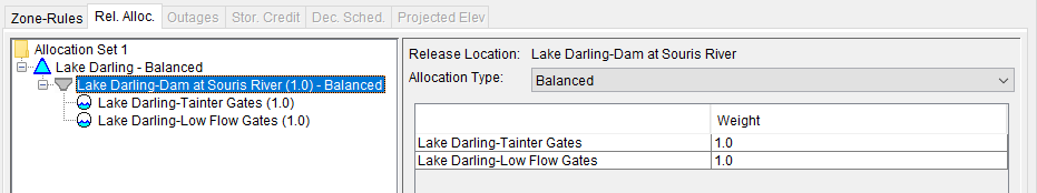
Figure: Release Allocation Editor - Balanced Allocation - Even Balance Example
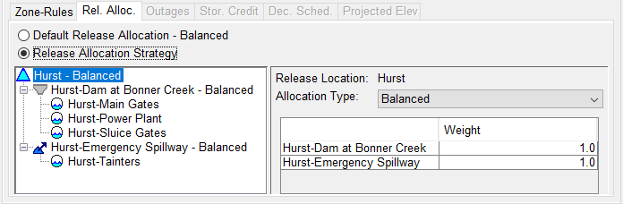
- In the outlet tree at the left, select the group for which you want to define the allocation scheme. The group may be the reservoir itself, the dam, or an outlet group that you defined in the reservoir's outlet hierarchy on the Physical tab of the Reservoir Editor. The release allocation is defined at all but the lowest level of the outlet hierarchy.
- Next, select the Allocation Type and specify the associated weights or order for the outlets or outlet groups within the selected group. Your options are:
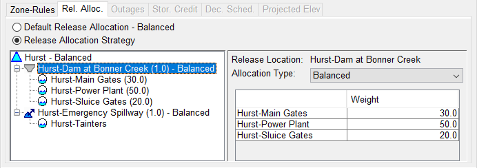
Balanced: Each outlet in the outlet group is assigned a Weight for the Balanced allocation method. The weights, entered in the table to the right of the outlet hierarchy tree, will be used to distribute the outlet group's release between its outlets. ResSim will normalize the values entered in the table to produce a set of factors that are then applied to the group's total release to produce the release for each outlet within the group.
In the example illustrated in "Figure: Release Allocation Editor - Default Allocation - Balanced" and "Figure: Release Allocation Editor - Balanced Allocation - Uneven Balance Example", the Allocation Type for Rafferty Reservoir-Dam is Balanced. The weights specified in the table for Rafferty Reservoir-Dam define an uneven balance (or distribution) among the available outlets in the Dam; the Main Spillway Gate is allocated 50% of the release from the Dam while the Low Flow Gate and Irrigation outlet are allocated 30% and 20% of the Dam release, respectively.

Figure: Release Allocation Editor - Balanced Allocation - Uneven Balance Example
While the weights do not have to add up to 100 (the values will be normalized during the release allocation computation), setting the weights such that they add to 100 makes it easier to understand the release allocation logic.
Sequential: To define the Sequential allocation type, the available outlets are assigned an order of priority, indicating which outlet gets the release first. When the first outlet it reaches capacity, the next outlet gets the remainder of the release until it reaches capacity, and so on.
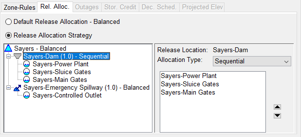
In the example illustrated in "Figure: Release Allocation Editor - Sequential Allocation Example", the group called Rafferty Reservoir has been assigned the Sequential Allocation Type, and the outlets within that group have been ordered so that releases are made through the Diverted Outlet first, and then after the diverted outlet reaches capacity the rest of the release is made through the Dam.
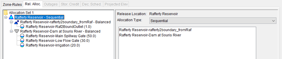
Figure: Release Allocation Editor - Sequential Allocation Example
To set up the Sequential allocation type and define the order of the outlets:
- Highlight the appropriate component (e.g., the "Reservoir") in the left panel of the editor.
- In the right panel of the editor, select Sequential from the Allocation Type selector. Below the Allocation Type selector, a text box will display the list of outlets in the selected outlet group.
- Select an outlet in the list and use the arrows located on the right side of the textbox to move the outlet up or down in the list. The outlet at the top of the list will be the first to release (up to its capacity), then the next outlet in the list will release (if needed, up to its capacity), and so forth.
Stepped: The Stepped allocation type is a combination of the Balanced and Sequential allocation types. It allows the user to specify how releases are allocated based on the total release that is required from the reservoir. For example, the user may specify one allocation for releases up to 5,000 cfs, one allocation for releases between 5,000 and 10,000 cfs, and another allocation for releases greater than 10,000 cfs.
The distribution of the group's total release across its outlets, and varying by step, is defined using a column for each outlet and rows describing the steps (or ranges of outlet capacity). A dropdown menu that defines units for values entered can be selected from the Table Units selector. The Stepped allocation method is designed to allow two or more options for the Table Units, although only one option has been implemented for ResSim version 3.3—% Release Capacity.
To define the Stepped allocation method, enter values into the table, in decreasing order of % Release Capacity, to describe how the total release to the group should be distributed to each outlet. Each value represents that outlet's share of the total release that its row in the table can accommodate.
The table always starts with a row in which a value of 100% is entered for each outlet. This means that if the total release assigned to the group is equal to the sum of the total capacity of each outlet, then each outlet will be allocated 100% of its capacity to release.
Enter values in each succeeding row such that the % Release Capacity value for at least one of the outlets is less than the value entered for that outlet in the previous row. The sum of the flows represented by the % capacity value for each outlet in a given row equals the total release that can be made by the group using that row's distribution.
If needed, additional rows can be added to the table by right-clicking in a cell of the table and selecting Insert Row(s) or Append Row from the table's context menu. Insert Row(s) will add the number of (blank) rows you specified into the table above the row of the cell from which you accessed the context menu. Append Row will add a blank row below the last row of the table.
It is not necessary to enter a final row where the allocation to each outlet is 0% since that will by assumed by ResSim. However, that (assumed) last row (of all zeros) represents a total group release of 0 cfs.
At each timestep, ResSim will calculate the release that each value in the table represents based on the current release capacity of the associated outlet. It then sums these release values by row to determine the total release that can be made by the group using that row's distribution. Next, ResSim determines the two successive rows that bound the total release allocated to the group and uses linear interpolation to determine the release each outlet will make.
Although defining the data for the Stepped allocation type is not as intuitive as defining the other two allocation methods, the following example should clarify how the data will be used and thus help you to determine the values to enter to produce the desired allocation.
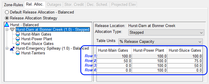
In the Stepped release allocation example shown in "Figure: Release Allocation Editor - Stepped Allocation Example", the Sayers-Dam outlet group has been assigned the Stepped allocation type and the table is filled with values (in units of % Release Capacity) to define how the total release to the group should be divvied up between the outlets. To understand how these values will be used, read the entries in the table from bottom up.
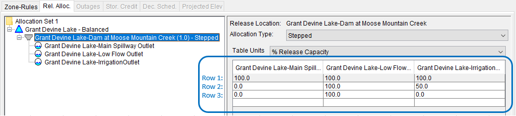
Figure: Release Allocation Editor - Stepped Allocation Example
The bottom row (row 3) indicates that the total dam release, if less than or equal to 100% of the Low Flow Outlet's capacity, should go to the Low Flow Outlet.
The next row up (row 2) indicates that if the total dam release is less than or equal to 100% of the Low Flow Outlet's capacity plus 50% of the Irrigation Outlet's capacity, the releases to Grant Devine Lake-Dam are intended to go to the Low Flow Outlet first and then to the Irrigation Outlet.
The next row up (row 1), as well as the top row (row 1), indicate that if the total dam release is greater than the sum of the Low Flow Outlet's capacity plus 50% of the Irrigation Outlet's capacity, the excess is shared between the Irrigation Outlet and the Main Spillway. The distribution of that excess between the Irrigation Outlet and the Main Spillway appears to be 1:2, but it's not quite that simple because the values in the table are not % Total Release but rather % Release Capacity. As such, the weighting of the release between the two outlets is a function of their capacity at any given time.
The significance of the use of % of Release Capacity can be seen by looking at at the arithmetic for the state of the system at timestep i :
- The Low Flow Outlet's release capacity = 5,000 cfs
- The Irrigation Outlet's release capacity = 5,000 cfs
- The Main Spillway's release capacity = 20,000 cfs
Using these capacities, the table of releases computed for the timestep is:
Row # | Main Spillway | Low Flow Outlet | Irrigation Outlet | Total Release |
1 | 100: 20000 | 100: 5000 | 100: 5000 | 30000 |
2 | 0: 0 | 100: 5000 | 50: 2500 | 7500 |
3 | 0: 0 | 100: 5000 | 0: 0 | 5000 |
If the total release to the Dam is 9000 cfs, then the release falls between rows 2 and 3. Using linear interpolation with the data in rows 2 and 3, the calculations for divvying up the 9000 cfs release are:
- Total Flow Ratio = (9000 – 7500)/(30000 – 7500) = 0.06667
- Power Plant = 5000 + 0.06667 x (5000 – 5000) = 5000
- Sluice Gates = 2500 + 0.06667 x (5000 – 2500) = 2666.66
- Main Gates = 0 + 0.06667 x (10000 – 0) = 1333.33