In the Watershed Setup Module you can define the Watershed Schematic Elements (Projects, Computation Points, and Impact Areas) used by ResSim and by other models that may share the watershed.
The ResSim Map Toolbar provides the tools for drawing and editing the geographically-referenced schematic elements in the Map Display area. The drawing tools also provide access to context menus for managing the schematic elements directly from the map display.
When you add a Project (reservoir, diversion, etc.) to the Map Display, it becomes part of the active configuration (the one displayed in the Configuration selector on the Module bar). A "superset" of all configurations is named Study and includes all of the Projects for the watershed; although not technically a configuration, if you have not created a configuration, Study will be selected as the active configuration by default. For more information on associating projects with Configurations, refer to "Reservoirs".
Of the watershed schematic elements, ResSim models only use computation points, reservoirs, and diversions.
Creating the other schematic elements will be described later in this chapter.
Creating Watershed Schematic Elements
To create or edit the watershed schematic elements you must be in the Watershed Setup module:
- Select Watershed Setup from the Module selector on the Module Bar
Configuring the Appearance of Watershed Schematic Elements
You can configure the appearance of Reservoirs, Levees, Diversions, and Computation Points in the Study Layer of your watershed using the Drawing Properties Editor ("Figure: Drawing Properties Editor").
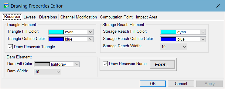
To access the Drawing Properties Editor:
- Select Drawing Properties… from the Edit menu of the Watershed Setup module, or
- Select Properties from the context menu of the Study layer in the Layer Selector.
See "Working with Map Display Layers" for details on how to change the drawing properties for your configuration elements.