Download PDF
Download page Using Merge and Split Tools to Customize Subbasin and Reach Delineation.
Using Merge and Split Tools to Customize Subbasin and Reach Delineation
Last Modified: 2025-01-28 08:31:15.428
Software Version
HEC-HMS version 4.13 beta.4 was used to create this tutorial. You will need to use HEC-HMS version 4.13 beta.4, or newer, to open the project files.
Project Files
Continue using your current project file from Preprocessing Terrain Data to Delineate Subbasin and Reach Elements.
Overview
In this tutorial you will customize the subbasin and reach delineation that was created by the automated delineation. Both the merge and split tools will be used.
Refine Subbasin and Reach Delineation using Merge
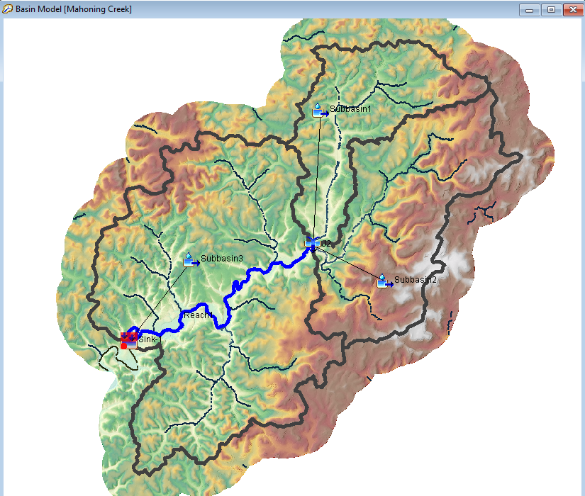
Using the default stream threshold (5 square miles) resulted in 17 subbasins and 8 reaches for the drainage area upstream of the Mahoning Creek at Punxsutawney stream gage. We will model the area with only three subbasins, Stump Creek, East Branch Mahoning Creek, and the local area downstream of the confluence. The following figure shows the locations of the Stump Creek, East Branch Mahoning Creek, and the Mahoning Creek Local subbasins. We will use the basin and reach merge capabilities within HEC-HMS to combine subbasins and reaches. Elements must be adjacent to each other for the merge operation to work. Reaches should have an upstream-downstream relationship. Subbasins can be side-by-side adjacent (if the merge produces a logical single outlet) or upstream-downstream so that the outlet for the merged sub-basin is the same as the lower subbasin.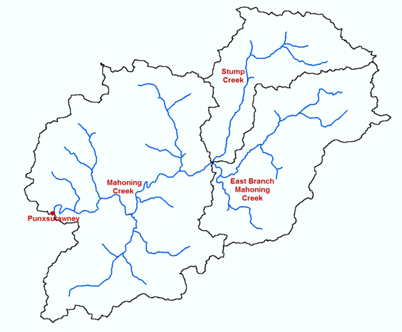
- Open the Punxsutawney project and then open the Mahoning Creek Basin Model.
To merge subbasins or reaches, select the first element by clicking on it with the arrow tool,
 . Holding down the SHIFT key, select the second element.
Subbasin Selection
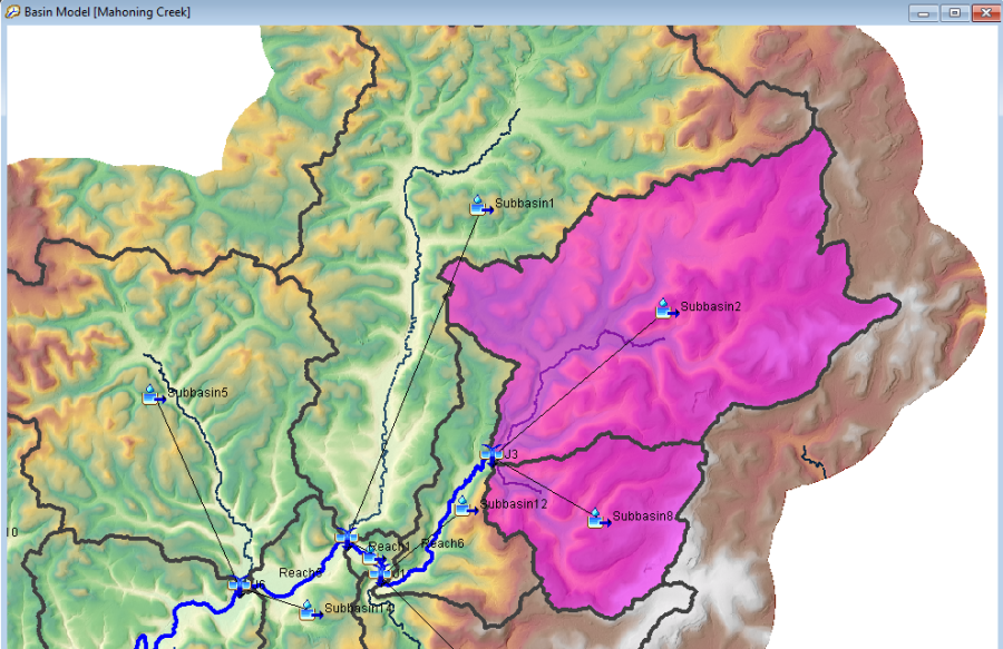
The default highlight color that appears when selecting a subbasin element within the basin model map pane is light gray which may be difficult to see. The highlight color can be changed by clicking Tools | Program Settings | Basin Map and changing the highlight color to something more visible, such as magenta.

After adjacent subbasin elements are selected, they can be merged by going to the GIS menu and selecting Merge Elements. Continue to merge all subbasins within the Stump Creek, Mahoning Creek and Mahoning Creek Local subbasins. You can merge two or more subbasin elements at one time, as long as all subbasin elements are adjacent and hydrologically connected. After merging the subbasins, merge river reaches within the Mahoning Creek Local subbasin so that there is only one reach. You might have a few unconnected junctions left over when merging subbasin elements. Delete any unconnected junction. When finished, there should be one subbasin and one reach below the confluence of Stump Creek and East Branch Mahoning Creek.

Subbasin Merges
Two or more subbasin elements may be merged at one time, as long as all selected elements are adjacent and hydrologically connected (share a common drainage point). If an element is accidentally selected that is not adjacent or hydrologically connected, the subbasin merge will not be allowed.
Reach Merges
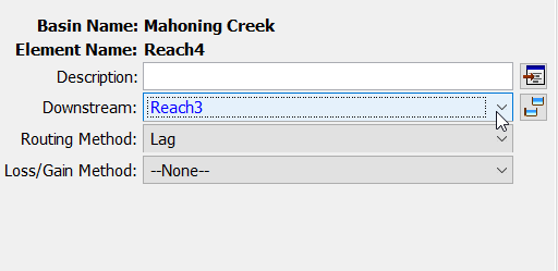
Two or more reach elements may be merged at one time, as long as all selected elements are adjacent and hydrologically connected by a junction or are directly connected as shown in the component editor below. If the connecting junctions are deleted before the reaches are merged, you must connect the reaches directly.
Refine Subbasin and Reach Delineation using Split
Now, we will use the split tool and delineate additional subbasin locations within the Stump Creek watershed. Sometimes, you will find additional flow gage information and need to modify the watershed delineation. Two "fictional" flow gages were found, and we need to modify the delineation in the Stump Creek watershed. Add the DelineationPoints shapefile to the Basin Model Map. The shapefile is in the …\Punxsutawney\data\GIS Data directory. The following figure shows the location of the two flow gages, Point 1 and Point 2.
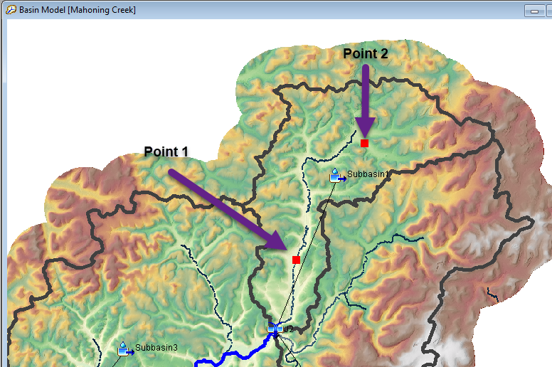
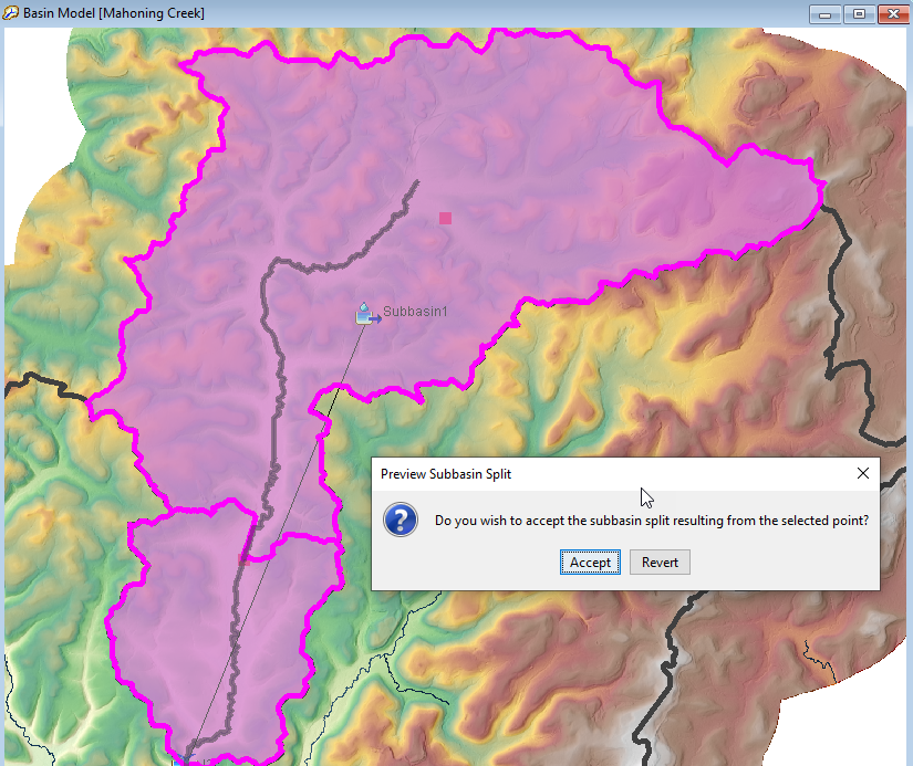
- You will notice Point 1 falls on top of the existing Identified Streams layer. Using the Arrow tool, select the Stump Creek subbasin element and then select the GIS | Split Element menu option. You will notice your mouse curser turns into a cross hair. Click on top of the Point 1 location, which should be located within an identified streams grid cell. Make sure you are zoomed in far enough to click within an identified stream grid cell. A message dialog will open asking if you want to proceed with the delineation. Click Accept.
- Zoom into Point 2. You will notice Point 2 does not fall on top of the Identified Stream layer.
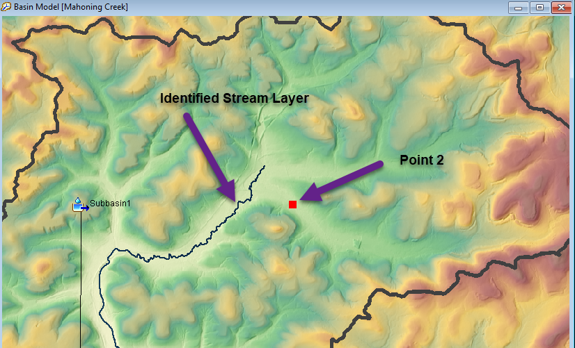
Turn on the Flow Accumulation grid to see the detailed stream network.
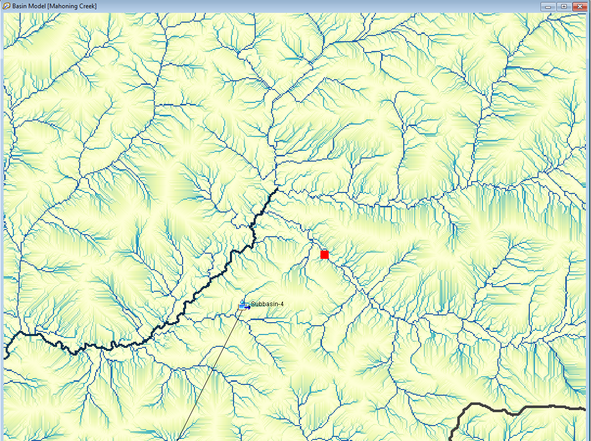
- Use the Split Elements tool to add a subbasin outlet at Point 2. Make sure you zoom in enough when adding a subbasin outlet at Point 2 that you click on a grid cell within the flow accumulation grid. The program will delineate a new subbasin with an outlet at Point 2. There should be one subbasin upstream of Point 2, one subbasin between Point 1 and Point 2, and one subbasin between Point 1 and the outlet of Stump Creek.
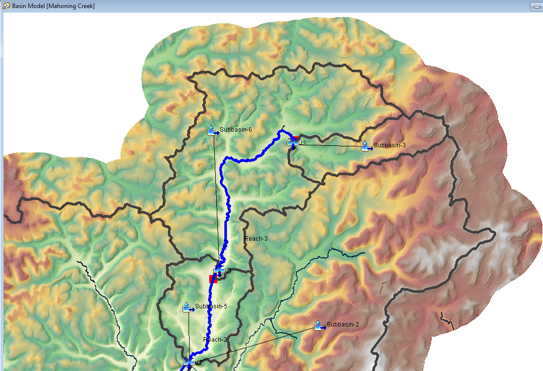
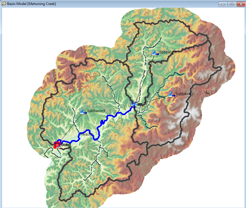
- Adding delineation points 1 and 2 was just an exercise to demonstrate how to force subbasin outlets to be located at gage sites or points of interest. Merge the three subbasins in the Stump Creek watershed so that the delineation matches the below figure.
Question:
1) Is there a faster way to reduce the number of elements than merging elements manually?
You can re-run the Identify Stream tool and use a larger stream threshold. Then you would re-run the Delineate Elements tool. The program will re-delineate the subbasin and stream network each time the Delineate Elements step is run.

Continue to Finalizing the Hydrologic Network