Download PDF
Download page Preparing Terrain Data for HEC-HMS using ArcMap.
Preparing Terrain Data for HEC-HMS using ArcMap
Overview
In this tutorial you will use ArcMap to prepare terrain data in the form of Digital Elevation Model (DEM) raster from open-source elevation and watershed boundary data (see the tutorial on Downloading Elevation and Watershed Boundary Data). Other GIS applications such as QGIS can be used instead of ArcMap. Refer to Downloading and Preparing Terrain Data for HEC-HMS Using QGIS for guidance. A DEM is a representation of the bare ground topography (elevations) excluding trees, buildings, and any other surface objects. We will use it as an input to HEC-HMS to create a terrain dataset, which can then be loaded into a Basin Model for hydrologic analysis (see Creating and Linking Terrain Data into a Basin Model tutorial). We will use the watershed boundary to clip the extent of the terrain raster for smaller file sizes and faster processing.
Background
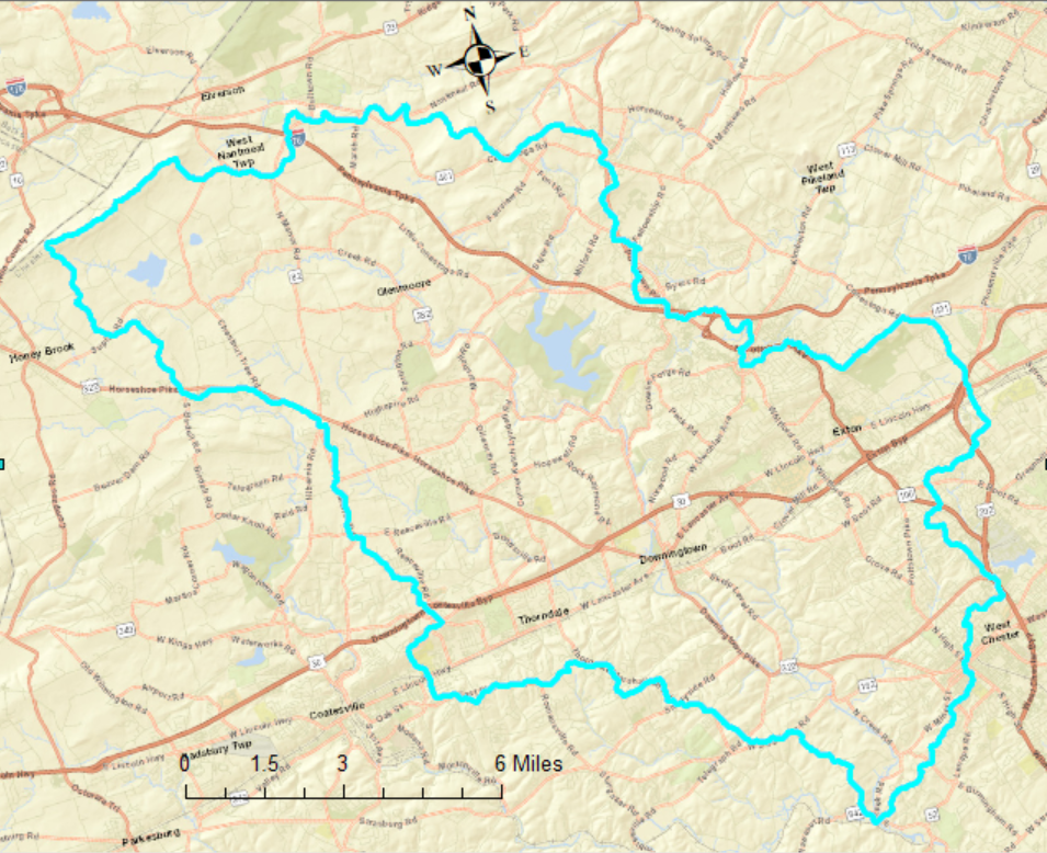
The watershed used in this example is the 122 square mile East Branch Brandywine Creek watershed in Pennsylvania.
Process the Elevation Data
This example uses ArcMap to merge, clip, and project the DEM file.
- Start a new project or open an existing project in ArcMap. It is helpful to save the map in the same folder as the rest of the project data.
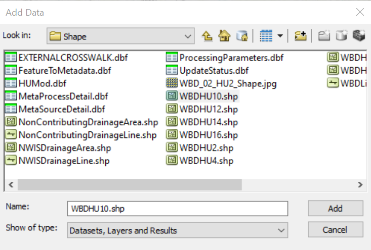
Import terrain and watershed boundary data from previous steps (HUC-10 level shapefile used in this example) to your project with Add data
 menu.
menu.Do not project the layers yet.
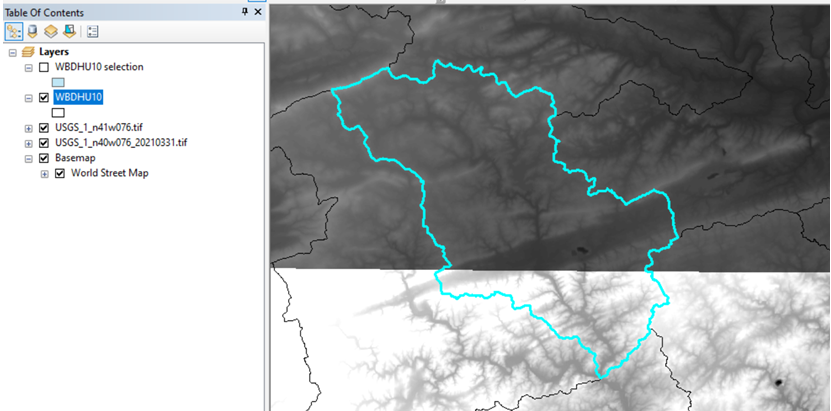
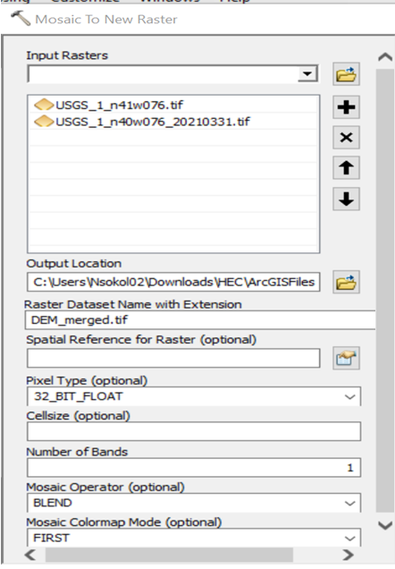
Merge multiple terrain files. This step is only necessary if you downloaded more than one terrain data set (two in this example). Use the Mosaic To New Raster (Data Management) tool to create a single raster.
- Set the Pixel Type field to 32_Bit_Float.
- Leave the Spatial Reference and Cellsize fields blank.
- Use *.tif extension for export.
- Set the Number of Bands to 1.
- Set the Mosaic Operator to Blend (the output cell value of the overlapping areas will be a horizontally weighted calculation of the values of the cells in the overlapping area).
- Use the Project Raster (Data Management) tool to re-project the terrain raster.
- Be sure to use either the Bilinear or Cubic 'Resampling Technique' (the other options are for categorical data, not terrain data).
Export the projected raster as a *.tif file.
Raster file names have length and other limits (such as not starting with a number).
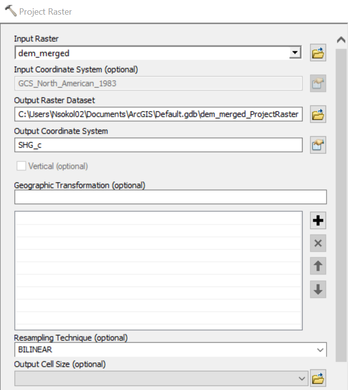
Select an appropriate coordinate reference system (CRS) under 'Output Coordinate System'.
A projected CRS should be selected. For example, the USA Albers Equal Area Conic USGS Version Linear Unit: Foot_US (0.3048006096012192) is routinely used by USACE within hydrologic modeling applications because this CRS preserves area, which is crucial for hydrologic modeling.Do NOT use an unprojected CRS, such as Geographic.
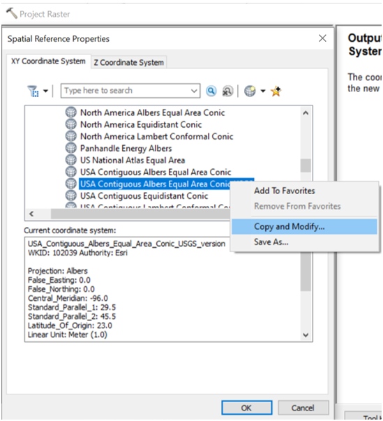
You can change the units in the raster projection to feet if desired. In Project Raster (Data Management) tool:
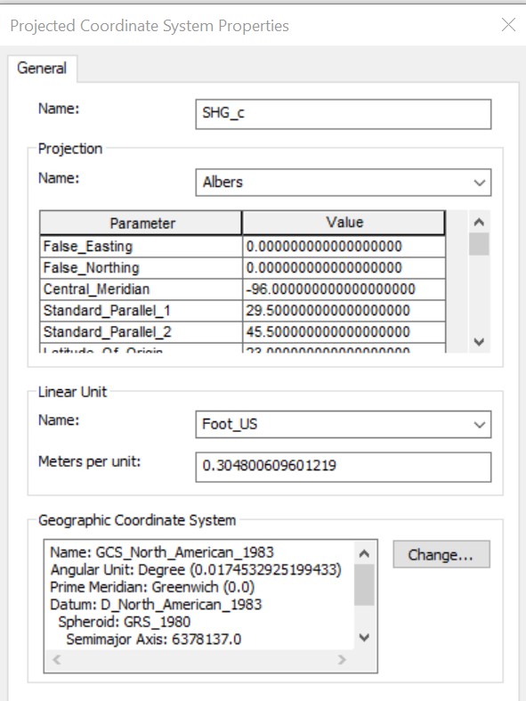
Right click on the chosen projection and select 'Copy and Modify' to save a copy of the projection named SHG_c (Standard Hydrologic Grid) in this example.
Double click on the new copy, change Linear Units to foot_US and click ‘Ok’.
Right click on the new copy to ‘Add to Favorites’.
Select the saved projection as the 'Output Coordinate System' from Favorites.
- Use the Project (Data Management) tool to project the watershed boundary shapefile to the same CRS as the terrain data.
- Specify the same projection and settings as the elevation/terrain raster, e.g. use the modified USA Albers Equal Area Conic USGS Version projection (SGH_c) that you added to Favorites in the last step.
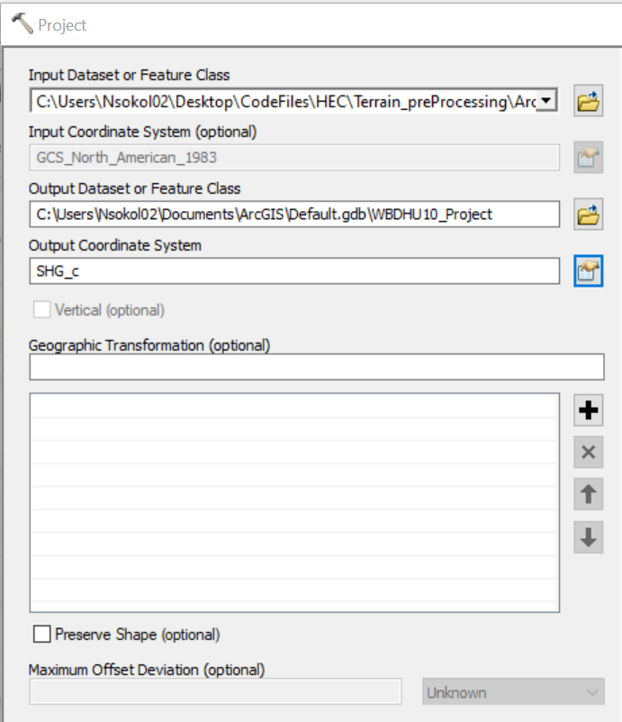
- Specify the same projection and settings as the elevation/terrain raster, e.g. use the modified USA Albers Equal Area Conic USGS Version projection (SGH_c) that you added to Favorites in the last step.
- Create and buffer a shapefile that encompasses the area of interest.
- This shapefile will be used as a boundary to clip the terrain raster in the next step.
- With the ‘Select’ tool
 , select the watershed of interest (East Branch Brandywine Creek in this example) from the WBDHU10 watershed boundary shapefile that was downloaded from the USGS National Map Viewer.
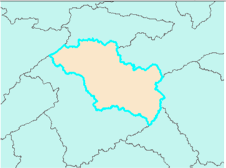
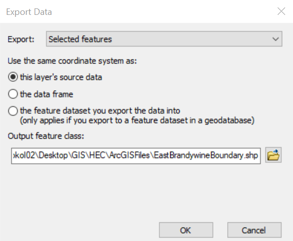
- Save as separate shapefile.
- Right click on the layer and select Data => Export Data (Selected features) from the dropdown menu.
- Check the box next to Use the same coordinate system as: 'this layer's source data'.
- Select ‘yes’ to add the data as a layer.
- Buffer the area of interest by two miles to avoid edge effects within the area of interest and save the buffered shapefile in Buffer (Analysis) tool.
- Set Distance to Linear unit = 2 miles.
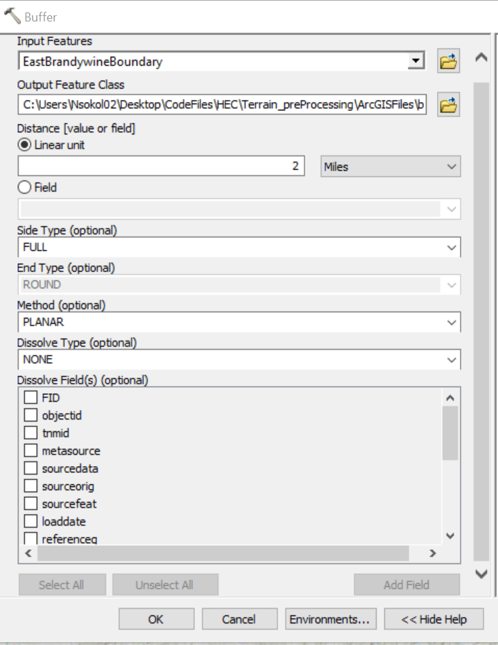
- Set Distance to Linear unit = 2 miles.
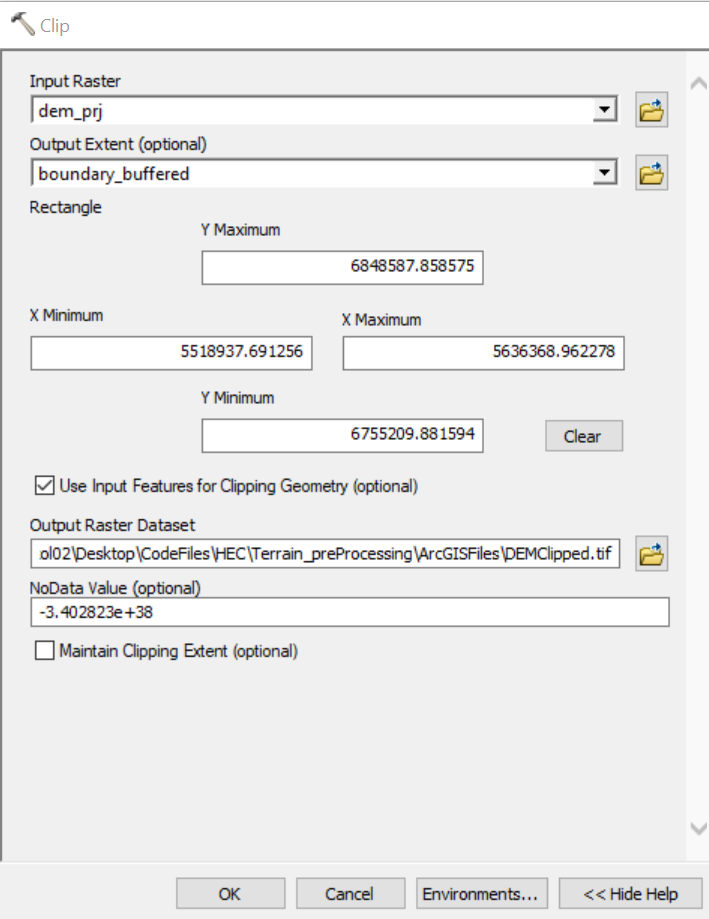
- Clip the projected terrain raster with the Clip (Data Management) tool, using the buffered boundary shapefile from the previous step. This step helps reduce the size of the terrain model and subsequent GIS processing time.
- Save the clipped raster as a *.tif file.
- Be sure to select the Use Input Features for Clipping Geometry (optional) check box (otherwise the rectangular extent of the clipping layer will be used instead).
- Check for and replace missing elevation data with mean values using the Raster Calculator (Spatial Analyst) tool. The delineation tools require a continuous surface with no interior grid cells containing missing elevation values.
- Check for missing interior cell values by entering the conditional expression: Con(IsNull(“dem_clipped”), 1, 0). Look at the new raster layer and see if any grid cells have a value of 1. If they do have a value of 1, then that grid cell is missing an elevation value and needs to be filled in with an appropriate elevation value.
- Use the following conditional expression to fill in missing values: Con(IsNull(“dem_clipped”), Focal Statistics(“dem_clipped”, NbrRectangle(3,3), “Mean”), “dem_clipped”). This expression replaces missing values with the mean value in the 3-by-3 cell square around the cell containing the missing value.
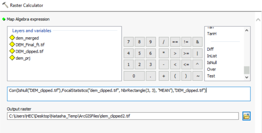
- You might need to run through additional iterations where you check if there are missing grid cell values, and then replacing the missing values with the average value from neighboring grid cells.
- (Optional) Convert vertical units of the clipped terrain raster to feet with the Raster Calculator (Spatial Analyst) tool.
- This step is optional since you can specify the vertical units in HEC-HMS. It is good practice for the horizontal and vertical units to be in the same unit system.
- Check the units on the elevation dataset – they can be found in the metadata section of the data source website, e.g. the vertical units are meters for the 1 Arc-second DEMs that were downloaded from the National Map Viewer in a previous step.
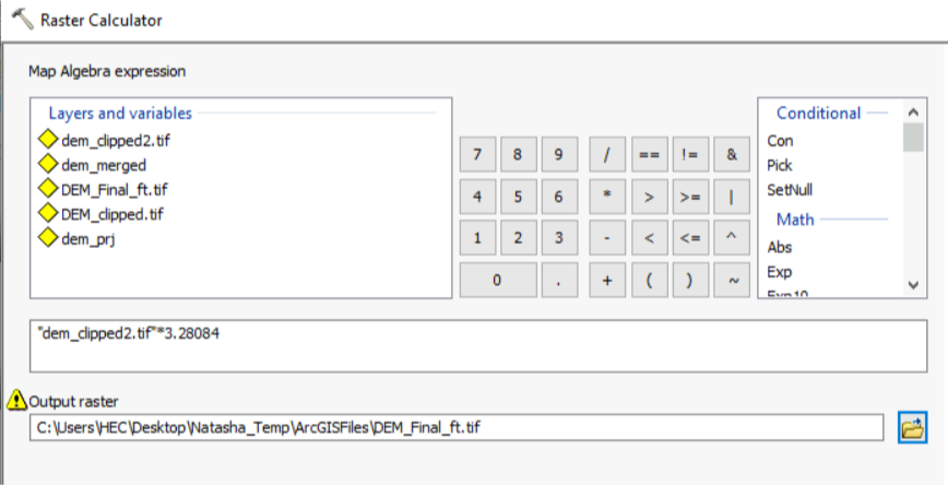
- Multiply the current raster values (DEM_clipped2.tif) by 3.28084 to convert from feet to meters.
- Save raster in *.tif format.
Import the New Terrain Dataset within an HEC-HMS Project
Import the *.tif terrain raster created in previous step (DEM_final_ft.tif) as new Terrain Data in HEC-HMS.
- Open or create a new project in HEC-HMS.
- Set the Default Unit System to U.S. Customary.
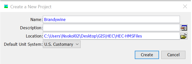
- Set the Default Unit System to U.S. Customary.
- From the Components menu, select Terrain Data Manager and create a new terrain dataset.

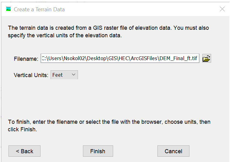
Click Next and browse to the final terrain *.tif file that was created in the previous steps.
Set the vertical units to feet if you converted the terrain raster elevations to feet.
Link the Terrain Dataset to a Basin Model.
In HEC-HMS, go to Components => Basin Model Manager to create a new basin model.

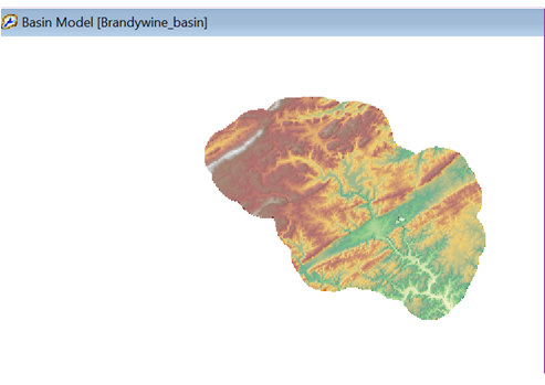
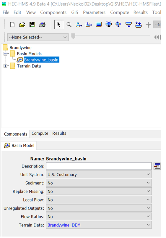
Click on the new basin model (Brandywine_basin) in the Watershed Explorer.
Within the Component Editor (lower left corner), select the terrain dataset (Brandywine_DEM) within the Terrain Data drop down menu.
Click the Save Current Project button.
If the Basin Model does not have a defined coordinate system, a popup menu will be shown.
Choose Skip to adopt CRS from the referenced GIS data (the terrain *.tif file). This option should be used 99% of the time. Use the other option to choose a CRS from an existing file.

The terrain data will now appear in the map model map and can be used to delineate elements, compute grid cells, and compute subbasin and reach characteristics.
