Download PDF
Download page Rule-Based Operations Routing.
Rule-Based Operations Routing
The Rule-Based Operations Routing Method is an extension of the Outflow Structures Routing Method that allows the outlet structures to be controlled using a set of rules. A reservoir can operate moveable gates to meet a number of objectives that can be seasonally-dependent, such as a desired volume of storage, limits or targets for releases, downstream controls, and so on. The reservoir structures with operable gates are the General Outlet, which is designed to duplicate outlet capacity curves from a water control manual; the Gated Orifice Outlet, and Sluice Gates and Radial Gates atop Broad-Crested or Ogee Spillways. The Rule-Based Operations method has all of the features and parameters of the Outflow Structures method, with the addition of Zones, as well as the option to use the General Outlet and Gated Orifice. Refer to the section of the documentation covering Outflow Structures for all other features.
The Rule-Based Operations routing method can be selected in the Reservoir Component Editor:
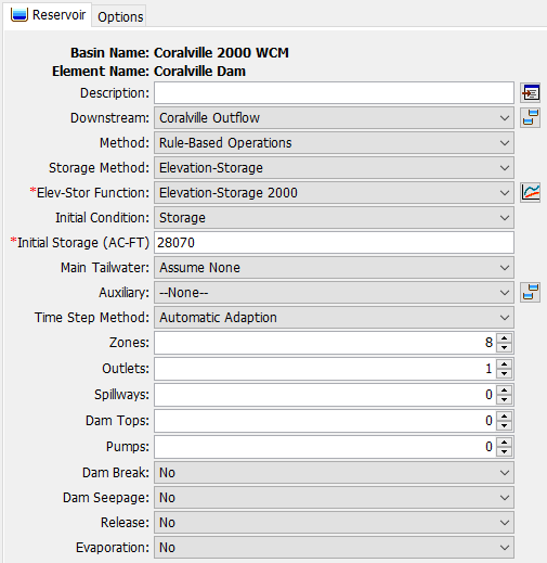
The Component Editor for this methods shares most of its functionality and features with the Outflow Structures routing method with a two notable differences. First, the inclusion of a Zone component, which implements rules, and extra outlet types not available in the Outflow Structures method.
Zones
Zones are sets of homogeneous operation rules. The day of the year of the simulation and the current pool elevation of the reservoir dictate which Zone the reservoir operations fall within. A reservoir may have as few as one Zone, and potentially very many Zones to handle operations that vary during low flow, flood events, or in response to seasonal conditions. By default a Reservoir element has no zones, but to use the Rule-Based Operations method you will need to add at least one Zone using the spinner box in the reservoir element's Component Editor. A typical Zone Component Editor is below:

Each Zone is defined by a maximum elevation, which is a Daily Elevation Pattern Paired Data curve. The reservoir identifies which Zone it is in based on the day's reservoir elevation, and finds the lowest Maximum Elevation curve above the current elevation. There can be blanks in the maximum elevation curve, which imply that the Zone is inactive for a given day.
Rules are added to a Zone by increasing the spinner. A Zone may have zero rules, in which case the reservoir only attempts to reach the storage objective (guide curve).
Storage Objective
Zones have at minimum a Storage Objective (also called a rule curve). A Storage Objective is implemented as a Storage Pattern Paired Data curve. It defines the reservoir's target storage for each day of the year. Typically a reservoir will have a single storage objective that can be applied to each Zone, but for flexibility, a different curve is allowed to be used for each Zone.

Rules
A Zone may have zero or more additional rules beyond a Storage Objective. There are eleven rule types that can be used.
| Rule Name | Usage |
|---|---|
| --None-- | Does not actually apply a rule. Generally don't use this. |
| Maximum Auxiliary Release | If you have specified any outlet structures to use a reservoir auxiliary, this controls the maximum amount that may be released in that direction. |
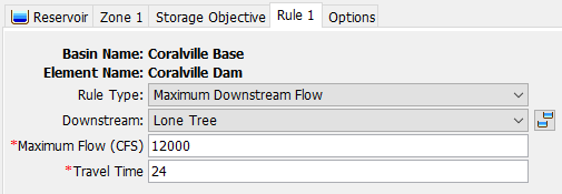
| Maximum Downstream Flow | Maximum allowed flow at a chosen element downstream of the reservoir. |
| Maximum Main Release | This controls the maximum amount of flow that may be released in the main release direction. |
| Maximum Rate Flow Change | Each time a gate change is made, this is the maximum amount the release is allowed to change. |
| Minimum Auxiliary Release | If you have specified any outlet structures to use a reservoir auxiliary, this controls the minimum amount that may be released in that direction. |
| Minimum Downstream Flow | Minimum allowed flow at a chosen element downstream of the reservoir. |
| Minimum Main Release | This controls the minimum amount of flow that may be released in the main release direction. |
| Specified Auxiliary Release | If you have specified any outlet structures to use a reservoir auxiliary, the reservoir will operate to release a specified amount in that direction. |
| Specified Downstream Flow | Specified target flow at an element downstream of the reservoir that you choose. |
| Specified Main Release | The reservoir will operate to release a specified flow in the main direction. |
Each rule has a Rule Type, and possibly additional parameters. For rules that are not downstream controls, they typically have one extra parameter, as in this Maximum Main Release rule editor:

For rules that operate for downstream controls, additional information is required:
Outlets
Four types of outlets are available in the Rule-Based Operations Routing Method. The General Outlet and Gated Orifice Outlet have operable gates. The other two outlet types are identical to the outlets in the Outflow Structures routing method.
General Outlet
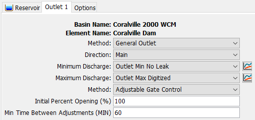
The General Outlet is a simple outlet method that depends on two rating curves: a Minimum Discharge curve and a Maximum Discharge curve. The reservoir operates a "virtual gate" that opens between 0 and 100%. At 0% and 100%, the reservoir releases the minimum and maximum discharges, respectively, for a given elevation. The release for gate openings between 0 and 100% is linearly interpolated.
Gate Method
The General Outlet has three gate methods: Adjustable Gate Control, Percent Annual Pattern, and Percent Time Series.
The Adjustable Gate Control requires the Initial Opening for the gate to be set and is used for initial release computations until a gate change is applied. The frequency of gate adjustments is defined by the Min Time Between Adjustments parameter.
Percent Annual Pattern is defined by a Percent Pattern Paired Data curve. This defines a pattern of gate openings expressed as a percent of the maximum. The gate settings are defined by the day of the year and repeated for every year in the simulation period.
Percent Time Series is defined by a Percent Gage Time Series. This defines a series of specified percent gate openings on a time-series basis instead of based on an annual pattern.
Gated Orifice Outlet
The Gated Orifice Outlet applies the orifice flow equations to a gate-controlled outlet. See the notes in the Orifice Outlet section of Outflow Structures Routing for details on this type of outlet. The gated version of this outlet offers four types of gate controls: Adjustable Gate Control, Fixed Opening, Percent Annual Pattern, and Percent Time Series. A typical Gated Orifice Outlet Component Editor is shown in the following figure.
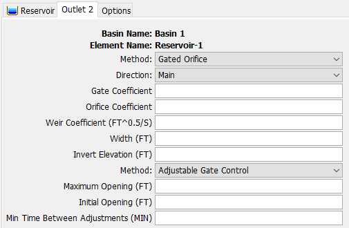
There are two dimensionless loss coefficients, the Gate Coefficient and the Orifice Coefficient.
When the outlet it not submerged, weir flow is applied, and the specified Weir Coefficient is used.
Two geometric parameters are required, the Width and the Invert Elevation. The Invert Elevation should be measured in the same vertical datum as the paired data functions defining the storage characteristics of the reservoir.
When the gate method is set to Fixed Opening, only one additional option is necessary, the Opening.
For adjustable gate methods, including Adjustable Gate Control, Percent Annual Pattern, and Percent Time Series, a Maximum Opening is required.
The Adjustable Gate Control requires the Initial Opening for the gate to be set and is used for initial release computations until a gate change is applied. The frequency of gate adjustments is defined by the Min Time Between Adjustments parameter.
Percent Annual Pattern is defined by a Percent Pattern Paired Data curve. This defines a pattern of gate openings expressed as a percent of the maximum. The gate settings are defined by the day of the year and repeated for every year in the simulation period.
Percent Time Series is defined by a Percent Gage Time Series. This defines a series of specified percent gate openings on a time-series basis instead of based on an annual pattern.
Spillways
Both the Broad-Crested Spillway and Ogee Spillway have the option to specify gates that control the flow over the spillway. The user can choose from Sluice Gates or Radial Gates to control the flow. The parameters and geometry for the spillway gates are the same as for Outflow Structures Routing and information can be found there.
With the Rule-Based Reservoir Operations routing method, four types of gate control methods are available: Adjustable Gate Control, Fixed Opening, Percent Annual Pattern, and Percent Time Series. The Component Editor for an Adjustable Gate Control applied to a Sluice Gate is shown below.
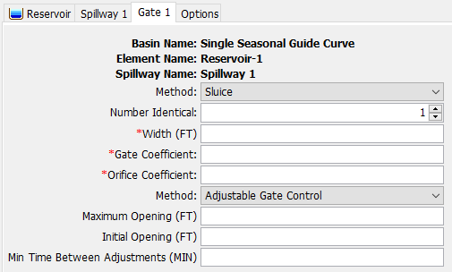
When the gate method is set to Fixed Opening, only one additional option is necessary, the Opening.
For adjustable gate methods, including Adjustable Gate Control, Percent Annual Pattern, and Percent Time Series, a Maximum Opening is required.
The Adjustable Gate Control requires the Initial Opening for the gate to be set and is used for initial release computations until a gate change is applied. The frequency of gate adjustments is defined by the Min Time Between Adjustments parameter.
Percent Annual Pattern is defined by a Percent Pattern Paired Data curve. This defines a pattern of gate openings expressed as a percent of the maximum. The gate settings are defined by the day of the year and repeated for every year in the simulation period.
Percent Time Series is defined by a Percent Gage Time Series. This defines a series of specified percent gate openings on a time-series basis instead of based on an annual pattern.