Part 3 – Define the FRA Simulation Input and Output Controls
Enable Linking between Models in the FRA Simulation
Now that we have the simulation, we need to do some additional steps to further specify how the simulation should run. In other words, we need to define how data is transferred from one model to another. We do this through the Model Linking Editor. Because we are creating an FRA simulation, the Hydrologic Sampler is creating the boundary conditions for the HEC-HMS model alternative instead of linking to externally provided DSS files, like we did in the deterministic compute yesterday. The other linkages are also slightly different due to the updating process of the watershed (to make the models run faster and for larger flow ranges).
1. Open the Model Linking Editor, from the Study Tree, by right-clicking on the Existing FRA simulation, pointing to Tools, and clicking Model Linking Editor from the shortcut menu.

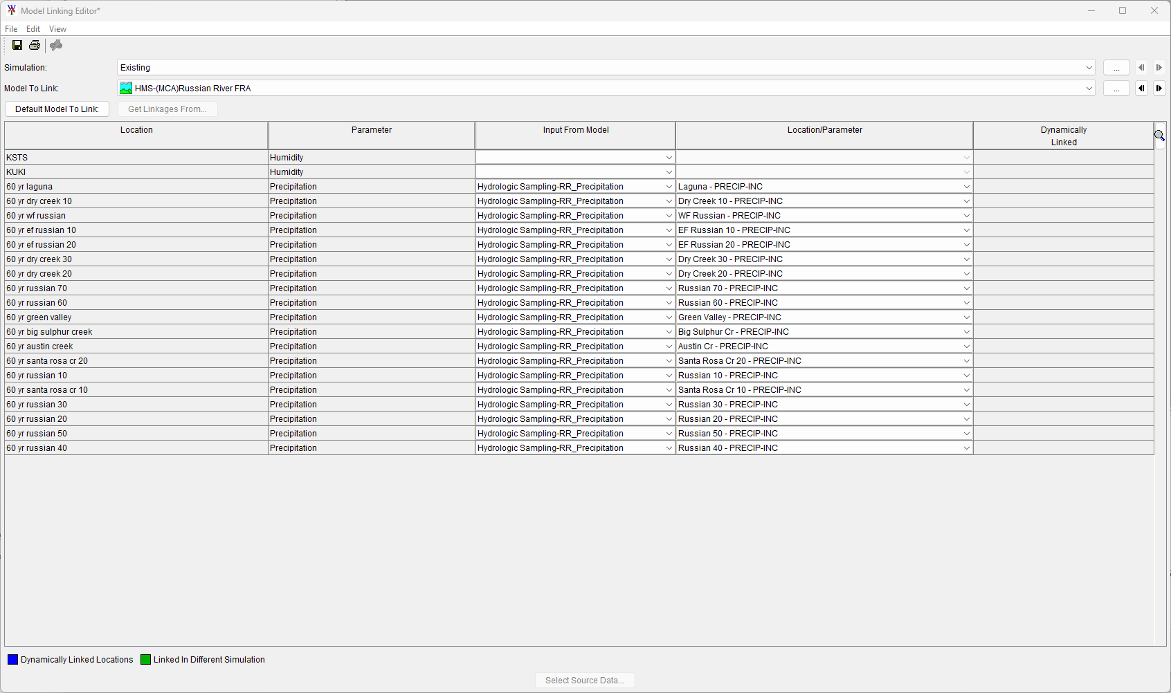
The Model Linking Editor opens.

2. From the Model To Link dropdown select Hydrologic Sampling-RR_Precipitation. Since the Hydrologic Sampler has all its boundary conditions defined in the alternative, there is no need to link it to any external files in the model linking editor; therefore, the table will be empty.
3. From the Model To Link dropdown select HMS-(MCA)Russian River FRA and the table should update, and it should be automatically linked to the Hydrologic Sampler. For this FRA simulation we do not need to change any of the automatic linking for the HEC-HMS model alternative. Leave the KSTS and KUKI blank.
4. Select the Model To Link as ResSim-Baseline_F and the table should update, and automatically link to the HEC-HMS model alternative for all but one location. The outlier location, Zero, should automatically link the Input From Model to the DSS File option; further, the linked DSS file allows for HEC-ResSim to compute based on zero inflow for the Known Flow parameter at location Zero. (Note, you can view the path and DSS file name for the selected DSS file by hovering over the Location/Parameter cell.)

5. Close the Model linking Editor, our models in the FRA simulation are now linked.
Create Model Skip Rules for the FRA Simulation
Our next step will be to define some skip rules. We are going to define these rules so that we can complete a full realization within the confines of this workshop. In order to complete the simulation in time, we need to eliminate a large percentage of the computes. This means we want to set up a skip flag rule. To open the Model Skip Rules Editor and define compute rules:
6. From the HEC-WAT toolbar, select the Model Skip Rules Editor ![]() icon.
icon.

The Model Skip Rules Editor opens.

We will build our logical expression to set our skip flag based on the maximum of the instantaneous precipitation at the Austin Creek location in the Hydrologic Sampler. For this workshop we will just specify the value to be 0.6, we will discuss the implications of this rule in the review or in later presentations.
The rule will take the form of: If maximum instant precipitation at Austin Creek <= 0.6 (inches), then for that event skip the HMS and ResSim model alternatives in the compute sequence.
To set the rule for the Existing FRA simulation:
7. First, we need to edit Expression A – click the Edit button for Expression A to elicit the Edit Logical Expression dialog.
- From the Edit Logical Expression dialog, for Expression A, click the Operator button.

- The Operator button adds two extra rows and in row 1 adds the expression "MAX(" to evaluate the Max. The enabled buttons will also change based on the currently selected row – make sure that row 2 is selected and click the Time Series button.

- The area below the table and buttons updates to allow users to select the Time Series Expression, select Time Series from Model from the dropdown list. The Select Time Series panel appears.
- From the Select Time Series panel, from the Model dropdown select the Hydrologic Sampler RR_Precipitation model alternative. The Time Series list appears for the selected model alternative; next, from the list select the "Austin Cr – PRECIP-INC" time series.
- Click the Save button to update row 2 of the table. Click OK to close the Edit Logical Expression dialog and return to the Model Skip Rules Editor.

- Note, the Expression A panel contains the entered logical expression as displayed in the figure below.

The Comparison Operator is automatically set to <= and does not need to be modified. However, to finish the logical expression we must set Expression B. To edit Expression B go to the Expression B panel and click the Edit button next to the panel. The Edit Logical Expression dialog opens.
- From the Edit Logical Expression dialog, for Expression B, click the Scalar button. The Scalar Expression dropdown is automatically set to Constant and does not need to be modified. From the Constant textbox, enter the scalar with the value of 0.6.

- Click the Save button to update row 1 of the table from the default value of 0.0 to the entered 0.6 value. Click OK to close the Edit Logical Expression dialog and return to the Model Skip Rules Editor. Note, Expression B panel contains the entered logical expression as displayed in the figure below.

8. From the Model Skip Rules Editor click the Save button to add the logical expression "MAX(Hydrologic Sampling:RR_Precipitation[Austin Cr – PRECIP_INC])<=0.6" to row 1 of the Build Logical Expression table.
9. Now we need to define which models to skip. From the Build Logical Expression table select row 2 of the table (which should have the condition of “END” as displayed in the figure below), and then from the Available Actions panel, click Select List of Models to Skip.

Below the Select Models to Skip panel, click the Select All button. Next, click the Save

10. Row 2 of the Build Logical Expression table updates with the names of the selected model alternatives. Make sure both model alternatives are displayed in row 2 and click OK to save the completed expression and close the Model Skip Rules Editor.
Define Output Variables for the FRA Simulation
Next, we need to define the Output Variables for the FRA simulation. These represent the scalar values that are computed as outputs for each event by each model which can be used as decision metrics. To identify the output variables:
11. Open the Output Variable Editor, from the HEC-WAT main window, from the toolbar click the![]() icon.
icon.

The Output Variable Editor opens.
12. For the Existing Simulation, select Hydrologic Sampling as the Model, and RR_Precipitation as the Alternative, and click the Select Variables to Save button. The Select Hydrologic Sampling RR_Precipitation Variables dialog opens.

13. From the Select Hydrologic Sampling RR_Precipitation Variables dialog, scroll to the bottom of the Available Variables list, select “Basin Average:Watershed 1 – AVG 8 DAY MAX precip” and click the Add The Output Variable Editor will update with the selected model output variable added to the first row in the table. Click OK, to return to the Output Variable Editor.
14. From the Model dropdown select HMS and the Alternative dropdown automatically updates. Click the Select Variables to Save button and from the Select HMS (MCA)Russian River FRA Variables dialog, select “WF Russian Outflow” and click Add. Click OK, to return to the Output Variable Editor.

15. Next, from the Model dropdown select ResSim and the Alternative dropdown automatically updates. Click the Select Variables to Save button and from the Select ResSim Baseline_F Variables dialog, select the following output variables:
- "Guerneville Gage Flow 6HOUR Flow"
- "Healdsburg Gage Flow 6HOUR Flow"
- "Lake Mendocino-Pool Elev 6HOUR Elev"
- "Lake Mendocino_OUT Flow 6HOUR Flow"
16. Click OK to add the four ResSim model alternative output variables to the Output Variable Editor.
17. Make sure the Frequency checkbox is checked for all six of the selected model output variables.

18. Save the selected output variables by clicking File | Save. Close the Output Variable Editor by clicking File | Close.