Task 2: Viewing HEC-FIA Inputs
The forecast you opened in the previous task has already been computed, so there is not much work that needs to be done. However, it is a valuable learning experience to see how things are connected. You are going to walk through a few of the inputs and how they are used by CWMS to communicate between the models in a forecast. Additionally, you will look at the structure inventory to see what is available to damage, and modify some of the inputs.
HEC-FIA Alternative Editor
To start, click on the Alternative button in the Action buttons list. Review the Alternative settings for a few minutes.
One thing you should notice in the HEC-FIA alternative is that the inundation configuration is titled GridsAndXSec. The inundation configuration in HEC-FIA defines how hydraulic parameters are handled during the compute. The HEC-FIA modeler can choose to provide inputs in the form of gridded data, cross sectional hydrograph data, or hydrographs at Common Computation Point (CCP) locations. This HEC-FIA model alternative was configured to use both grids and cross sections, and the modeler named the configuration to clearly identify that.
Each compute methodology has its strengths and weaknesses; for a full understanding of the various Inundation Configurations consult the HEC-FIA Documentation. Using gridded output from HEC-RAS typically provides the fastest and most accurate method for HEC-FIA to interpret hydraulics results at each structure. The cross section-only compute uses an interpolation routine in HEC-FIA. The CCP style of inundation configuration aggregates all the structure-damage information to the CCP locations, and provides the least accurate method of computing damage.
Model Linking Editor
To see how the HEC-RAS results are linked to HEC-FIA, open the Forecast menu and choose Model Linking. The Model Linking Editor should appear.
Select the Future Rain Forecast Run and then select FIA-Real-time as the model requiring input.

The editor identifies the three grids and three hydrographs used by HEC-FIA. The maximum depth grid is used to compute structure and content damages. The hydrographs inform impact response reports based on the Russian River gages used by the California Nevada River Forecast Center. The life loss calculations use the grids showing maximum depth, maximum depth times velocity, and arrival time of when depth reaches two feet; as well as the hydrographs at Healdsburg and Johnson's Beach which support rules about flood warning issuance.
The Location and Parameter columns are from the cross section editor database, and the Input From column indicates the data is coming from the RAS-Russian River Real-Time model alternative. Notice that the Location/Parameter column matched the Location and Parameter columns in the HEC-FIA version of cross section database. CWMS automatically attempts to link the HEC-RAS and HEC-FIA cross section locations when initially selecting an HEC-FIA alternative. The matching algorithm sometimes produces an incorrect linkage, so you need to review the results to ensure correct linking. The editor prints duplicated links in purple, making it easy to identify where to make manual corrections. The Model Linking Editor will show a lot of purple text when a systematic problem occurs. Remember that the HEC-RAS plan output locations must include each HEC-FIA input location. The appropriate grids must also be set up in RAS Mapper. The HEC-FIA model linking works best when the HEC-FIA modeling team and the HEC-RAS modeling team coordinate regarding the HEC-RAS output for the intended compute style in the HEC-FIA alternative before importing the models into CWMS.
Cross Section Time Series Mapping
To see how HEC-FIA stores the cross section linking, use the Cross Sections button on the Actions Tab to access the dialog window. This form is used to define the HEC-DSS linking for each cross section. The cross section shapefile is used to translate the hydrographs in HEC-DSS to a particular location on the floodplain. The three cross-sections represent locations where the HEC-FIA model requires hydrographs from HEC-RAS to support rules for Impact Response or Warning Issuance. Notice that the first column is named Location, this is what is used in CWMS to populate the Model Linking Editor.

Structure Inventory
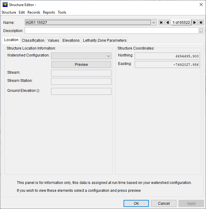
HEC-FIA computes damages on the individual structure level and then aggregates the damages by emergency planning zone or geographical boundary in the reports. Since structures are stored as individual structures, it is much easier to locate structures that were misplaced or poorly defined. This allows the QA/QC process to be substantially more robust than legacy methods (aggregated stage damage functions). To view the structure form editor select the Structure Form Editor action button. You can see the information in the HEC-FIA structure database through this form. Alternatively, you can right-click on a structure in the map window and select Edit Properties (switch to the Zoom Tool if necessary to adjust the view, then back to the Select Tool to right-click on the structure).

Impact Response Tables
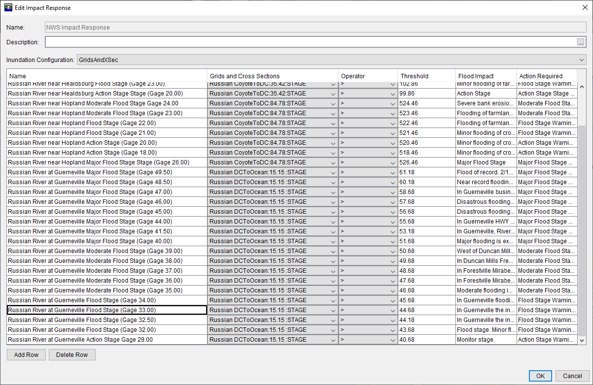
Open the Impact Response editor by clicking the Impact Response button on the Actions tab. The gage at Johnson's Beach (Russian River at Guerneville) has a defined impact at stage of 33 feet - the intersection of Highway 116 and Drake Road must be closed. You can find the source of this information from the link http://water.weather.gov/ahps2/hydrograph.php?wfo=eka&gage=GUEC1
Note
The gage datum shown by the NWS is in NGVD 29, but the HEC-RAS results are computed in NAVD88. NAVD88 elevations equal the Guerneville gage zero plus 11.68 feet.The Impact Response Table is shown below.

Critical Infrastructure
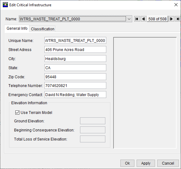
The HEC-FIA model has been developed to incorporate critical infrastructure elements within the study area. Open the Critical Infrastructure editor by clicking the Critical Infrastructure button on the Actions tab. From the Name drop-down list, select the element WTRS_WASTE_TREAT_PLT_0000. Note that typically the digital elevation map is used to determine the elevation at the point location of the critical infrastructure elements. This is indicated by the check box next to the Use Terrain Model option.

However, this assumption often turns out to be too simplistic and needs to be edited, so HEC-FIA allows modelers to manually define the elevation that causes flooding at the structure. For example, a ground elevation falling within the parking lot of the Wastewater Treatment Plant poorly reflects a river stage that causes backwater problems. Uncheck the box for Use Terrain Model and enter a ground elevation of value 70.0 to represent the river stage that triggers operations during high water. Click Apply and Ok.
Finally, to update the results of the forecast to reflect this change, use the Compute button on the HEC-FIA Action tab.
Prior Task(s):
Current Task:
Next Task(s):