Download PDF
Download page Spatial Data Visualization.
Spatial Data Visualization
Grid Sets
A grid set can be thought of as a sequence or time series of grids. Since a single HEC-DSS record of gridded data contains data for only one time interval, you must create grid sets within the watershed before you can view precipitation (or other data such as temperature) grids changing through time over the watershed. Grid sets are created by HEC-MetVue.
Adding a Grid Set
Once a grid set has been created for the watershed, you can add it to the Visualization Module for viewing in the Visualization Map Window.
To add a grid set to the watershed:
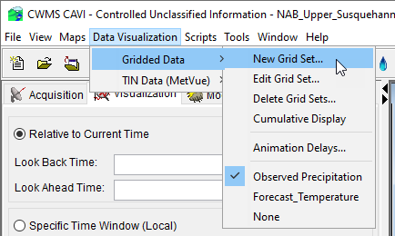
- On the Data Visualization menu, point to Gridded Data and then click on New Grid Set.

- The Create New GRID dialog will open. You must enter a Name for the new grid set, and a description for the grid set is optional. The new grid sets Directory will be automatically generated, but can also be modified.
- Click OK and the Create New GRID dialog will close.
- The Edit Grid Set dialog will open. Click Add File(s) and navigate to the available precipitation grid sets created in the HEC-MetVue program. Next set each of the Grid Set Identifiers listed using the drop-down options.
- Click OK and the Edit Grid Set dialog will close.
- The available Gridded Data sub-menu will list all of the available precipitation grid sets created from the HEC-MetVue program. To be available to the CAVI, a grid set must be defined using the CWMS file selection method, and cannot be associated with a fixed time window. The grid sets listed are the grid sets that you have chosen to associate with the watershed using New Grid Set option in the Gridded Data sub-menu.
Removing a Grid Set
To remove grid sets from the watershed:
- From the Gridded Data submenu, select Delete Grid sets and the Delete Object dialog will open.
- Select the grid set you wish to delete from the watershed. Click OK and the Delete Object dialog will close.
Selecting a Grid Set to View
To select a grid set:
- On the Visualization menu, point to Gridded Data.
- At the bottom of the submenu, you will see the names of the grid sets that you have added to the watershed. Select the grid set you wish to view. None displays no precipitation grids in the Map Window.
- When you select a grid set for viewing, a checkmark will appear beside its name in the list.
Controlling Properties of a Grid Set
You can control the visibility and color scheme of the grid set through the Map Layers dialog (see Understanding Layers for more information about layers). In the Visualization Module, the Map Layers dialog shows your selected grid set layer. In addition, you can control the color scheme, tic intervals, and the minimum/maximum values for the contour limits from the Gridded Data layer.
To change a grid set's properties:
- From the Maps menu, click Map Layers and the Map Layers dialog (Map Layers Editor) opens.
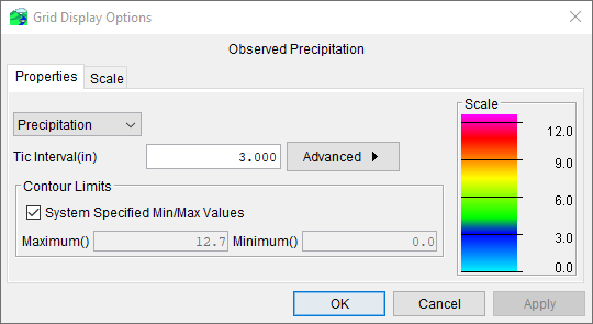
- From the tree, right-click the grid set layer. From the shortcut menu click Properties. The Grid Display Options dialog opens.

- The name of the active grid set is displayed at the top of the Grid Display Options dialog.
- The drop-down list at the top left of the Properties tab contains seven pre-set color contour schemes, with the default being Precipitation.
- You can set the tic interval by entering a value in the Tic Interval field.
- In the Contour Limits panel you can set the minimum and maximum contour values. By default, CWMS automatically determines the minimum and maximum contour values. If you wish to enter these values manually, uncheck the box next to the System Specified Min/Max Values option and enter values in the Maximum and Minimum fields.
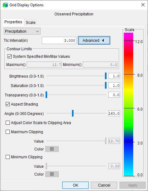
- For other setting options, click Advanced. The Grid Display Options dialog expands to include options for brightness, saturation, transparency, aspect shading, maximum clipping, and minimum clipping.

- You can control the Brightness (the amount of white, measured from 0.0 to 1.0), Saturation (the amount of black, measured from 0.0 to 1.0), and Transparency (the level of opacity or alpha, measured from 0.0 to 1.0) of your gridded data layer either by moving the sliders or by typing values into the text fields. The color scale to the right will update according to your selections.
- If you are using elevation maps, you may wish to choose Aspect Shading as your color contour scheme. Use the Aspect Shading option to make the elevation map appear in relief by placing an imaginary light source above the map and shading the elevation contours. When the Aspect Shading option is selected, you can use the Angle slider to adjust the angle of the light source.
- By default, the Maximum Clipping and Minimum Clipping options are deselected. If you activate these options, the Value sliders and Color buttons become available. The Value sliders allow you to specify the amount of clipping within the contour limits you have specified; you can also type values into the boxes. When you click on the Color buttons, the Color Chooser appears. For more information see Using the Color Chooser.
Controlling the Scale of a Grid Set
To set the visualization scale for the gridded data layer:
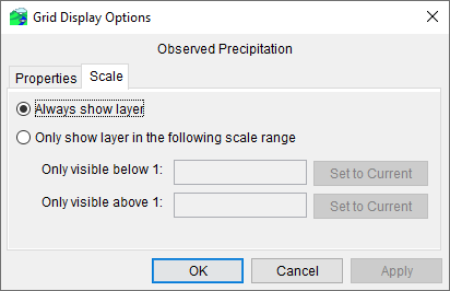
- Click on the Scale tab within the Grid Display Options dialog.

- The zoom-in and zoom-out scale factors can be set from this tab. By default the Gridded Data Layer is set for Always show layer. To see visualization scales click Only show layer in the following scale range.
- To set the scale so that the gridded data layer becomes visible as you zoom-in, you can set the scale to the current scale by clicking Set to Current. If you wish to enter a value, from the Only visible below 1 field, enter the scale factor.
- To set the scale so that the gridded data layer becomes visible as you zoom-out, you can set the scale to the current scale by clicking Set to Current. If you wish to enter a value, from the Only visible above 1 field enter the scale factor.
- Click OK, the Grid Display Options dialog closes, and the visualization scale is set for the gridded data layer.
HEC-MetVue TIN Data Display
The HEC-MetVue plugin allows for display of spatial data within the Visualization tab. In order to enable HEC-MetVue display within the Visualization tab, at least one HEC-MetVue Alternative containing at least one Map Panel must exist in the Setup tab. When properly configured in the Setup tab, the Data Visualization menu will have an entry for TIN Data (MetVue). This menu will be populated with the available HEC-MetVue alternatives, which will have further sub-menu items populated with the Map Panels within that alternative. These alternatives and Map Panels are contained in the HEC-MetVue project file located in the ./watershed/MetVue directory. Additionally, any edits to the HEC-MetVue settings performed from the Visualization tab will be placed in the HEC-MetVue project file located in the ./watershed/MetVue directory.
After selection of an HEC-MetVue Map Panel, information within the Map Panel will be displayed. In order to select data to display, clicking the Select Input Data button will display the data selector.
After selecting data with the Select Input Data dialog, the resulting HEC-MetVue image will be drawn in the Visualization map panel. Note that if there are multiple map windows for the Visualization tab, HEC-MetVue will only draw in the first map window. This prevents two map windows displaying duplicate data. The time window of the data is controlled by the time window settings of the Visualization tab, and clicking the Refresh button will cause the data to redraw in the map window.
Removing an HEC-MetVue image from a Data Visualization map window is performed by selecting the None option in the Data Visualization -> TIN Data (MetVue) menu.
Similar to the Modeling tab, several different action buttons become available when visualizing data from HEC-MetVue. For most of these buttons, the user can refer to Creating an HEC-MetVue Model Alternative, as HEC-MetVue behaves similarly in both the Visualization and Modeling tabs, with the exception of Save Data To Server.
Remote Data
The HEC-MetVue plugin provides support for visualizing and editing remote HEC-DSS data. This can be performed by loading remote data in the Select Input Data dialog and selecting a remote file, similar to the selection of remote data in a Grid Set. Since HEC-MetVue does not have server connection capabilities, it relies on the CAVI to download remote data to a local, temporary directory. Data will be copied into a temporary HEC-DSS file: ./watershed/MetVue/session/mappanel/temp_data.dss. After copying data to this directory, HEC-MetVue will read the data and display it in the map window. At this point, all editing options are available to the user. Once the user is done editing the data, the Save Data To Server button will push the edited data back to its original file on the server. When the CAVI is closed, any remaining temporary HEC-DSS files will be removed from the HEC-MetVue directory.