Download PDF
Download page Option 1. Temperature Index: Swamp Angel Study Plot, Colorado.
Option 1. Temperature Index: Swamp Angel Study Plot, Colorado
Return to: Introduction to Point Snowmelt Calibration
Last Modified: 2024-09-05 21:41:32.322
The simplest snowmelt/accumulation modeling approach within HEC-HMS, which has been available for several years, is the Temperature Index method. This method is based upon SNOW-17 (Anderson, 2006). Within this method, air temperature is used as a proxy for the energy available for heating or melting the snowpack. While this method is relatively simple, it is incredibly flexible, easily adjusted through model calibration, and has seen wide use throughout the U.S. to design and operate water supply and flood risk management infrastructure (USACE, 1998). The temperature index snow model within HEC-HMS requires temperature data at each time step, as well as initial snow conditions at the first time step of the model. Precipitation data is not required at every timestep, but it is recommended. Snow observations are useful for calibration of the snow meteorological model. These data may come from multiple sources and may require development prior to incorporation into the models. Precipitation in the form of rainfall or snowfall is determined by the HEC-HMS model based on the precipitation discrimination (PX) temperature. Temperature data are used as an index for all of the energy fluxes into the snowpack and they are used to determine whether precipitation falls as rain or snow, whether snow melts, and the rate at which melting occurs.
Create Paired Data Components
To parameterize the Temperature Index snowmelt model, you will create two Paired Data Components. These components will represent (1) the ATI-Meltrate Function that is used to describe the Dry Melt Rate and (2) the ATI-Coldrate Function .
- Select Components | Paired Data Manager.
- From the Data Type drop-down menu, select ATI-Meltrate Functions and click the New... button.
- Enter ATI-Meltrate as the name and click Create.
- From the Data Type drop-down menu, select ATI-Coldrate Functions and click the New... button.
- Enter ATI-Coldrate as the name and click Create.
- Close the Paired Data Manager window.
- In the Watershed Explorer, expand the Paired Data folder.
- Expand the ATI-Meltrate Functions folder and click the Meltrate node.
- In the Paired Data tab, make sure that the Units are set to DEG F-DAY: IN/DEG F-DAY.
- Click the Table tab and enter the values from the table below.
ATI-Meltrate Function
ATI (DEG F-DAY)
Meltrate (IN/DEG F-DAY)
0 0.02 100 0.05 500 0.10 - Click Save.
- Expand the ATI-Coldrate Functions folder and click the Coldrate node.
- In the Paired Data tab, make sure that the Units are set to DEG F-DAY: IN/DEG F-DAY.
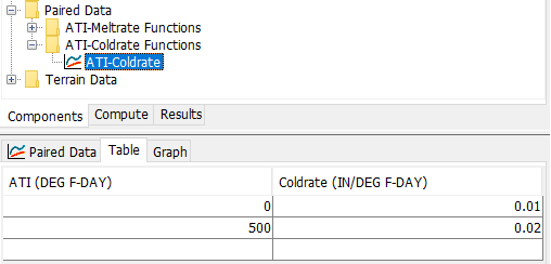
- Click the Table tab and enter the values from the table below.
ATI-Coldrate Function
ATI (DEG F-DAY)
Coldrate (IN/DEG F-DAY)
0
0.02
500
0.03
- Click Save.
Parameterize the Temperature Index Snowmelt Method
- Right click on the SwampAngel Basin Model and click Create Copy....
- Enter SwampAngel_TI as the name and click Copy.
- Expand the SwampAngel_TI node and click the SASP subbasin node.
- In the Component Editor, select the Subbasin tab.
- Change the Snow Method to Temperature Index.
- Leave all other methods set to --None--. We are only simulating snow accumulation and melt in this workshop.
- Expand the SASP subbasin node.
- Select the Temperature Index node in the project tree (or select the Snow tab).
Enter the following parameter values:
- Leave the Index field blank. This parameter is used to adjust the precipitation for orographic trends.
- PX Temperature (F): 32
- Base Temperature (F): 32
- ATI Coefficient: 0.98
- Wet Melt Method: Constant Value
- Wet Meltrate (IN/DEG F-DAY): 0.1
- Rain Rate Limit (IN/DAY): 0.1
- Dry Melt Method: ATI Function
- ATI-Meltrate Function: ATI-Meltrate
- Cold Limit (IN/DAY): 0.2
- ATI-Coldrate Function: ATI-Coldrate
- Coldrate Coefficient: 0.5
- Water Capacity (%): 5
- Groundmelt Method: Fixed
- Groundmelt (IN/DAY): 0
Right click on the Temperature Index node under the SASP subbasin node and select Add Elevation Band, as shown in the following image:

- Expand the Temperature Index node and select Band 1.
- Enter the following on the Band 1 tab:
- Percent (%): 100
- Elevation (FT): 11060
- Leave the Index field blank. This parameter is used to adjust the precipitation for orographic trends.
- Initial SWE (IN): 0
- Initial Cold Content (IN): 0
- Initial Liquid Water (IN): 0
- Initial Cold Content ATI (DEG F): 0
Initial Melt ATI (DEGF-DAY): 0
When using the Temperature Index snowmelt method, HEC-HMS requires the modeler define the percentage of the subbasin area within each elevation band. Since we are using a single elevation band for the SASP subbasin, the Percent (%) parameter should be set to a value of 100. Also, the initial snow model parameters can be set to zero because the simulation will start at the beginning of the water year (WY), when there is no snowpack.
Link the Basin Model to the Meteorologic Model
- Expand the Meteorologic Models folder.
- Select the WY2006 meteorologic model.
- In the Component Editor, select the Basins tab.
- In the SwampAngel_TI basin model row, select Yes from the drop-down menu. This links the WY2006 meteorologic model to the SwampAngel_TI basin model.
- Click Save.
Create and Compute a Simulation Run
- Select Compute | Create Compute | Simulation Run....
- Enter WY2006_TI as the name and select Next>.
- Select SwampAngel_TI Basin Model, the WY2006 Meteorologic Model, and the WY2006 Control Specifications.
- Click the Finish button.
- In the Toolbar, select the WY2006_TI simulation from the drop-down menu and click the Compute (exploding raindrop) button:

- When the simulation is complete. navigate to the Results tab.
- Expand the WY2006_TI node and then expand the SASP subbasin node.
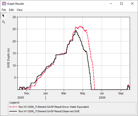
- Select the Observed SWE and Snow Water Equivalent time series nodes. Click the View Graph button, as shown in the figure below. Alternatively, select the Snowmelt Graph to view Precipitation, Air Temperature, Observed SWE, and Snow Water Equivalent in the same window.

You can edit the linestyle (e.g. color, symbol, etc) of a time series by clicking Edit | Plot Properties.
Question 1: Using the initial parameter values, how does your simulated SWE compare with the observed SWE? How will you use the preliminary results to inform your calibration approach?
Simulated SWE during the accumulation period matches the observed SWE fairly well. Simulated snow continues to accumulate after peak observed SWE occurred. As a result, simulated snow melt is also delayed relative to observed snow melt.

Calibration efforts should focus on modifying parameters that impact the rate of snowmelt, such as the ATI-Meltrate and ATI-Coldrate curves. In addition, the Base and PX Temperature parameters tend to have a large impact on snow accumulation and melt.
Calibrate the Temperature Index Parameters
Revisit the Temperature Index parameters that you defined in the previous task. Modify the parameter in a systematic way and keep track of the effect of the parameter modifications on the simulated SWE. To assist with calibration, plot the Precipitation, Air Temperature, Observed SWE, and Snow Water Equivalent time series using the Snowmelt Graph.
Attempt to increase the peak SWE by modifying the PX Temperature and Base Temperature.
Recall that the PX Temperature is used to discriminate between precipitation falling as rain or snow. Increasing the PX Temperature will cause more precipitation to fall as snow, resulting in a deeper snowpack.
When the air temperature is higher than the Base Temperature, snowmelt occurs. Increasing the Base Temperature will cause the snowpack to last longer since higher temperatures are required to melt the snow.
- Try increasing the PX Temperature to 34 deg F and rerun.
- Try increasing the Base Temperature to 34 deg F and rerun.
- Try reducing the PX Temperature to 30 deg F and rerun.
- Try reducing the Base Temperature to 30 deg F and rerun.
- Continue modifying to best match the peak SWE.
- Attempt to improve the rate at which snow melts and melt out date by modifying the Melt Rate ATI function.
- Try increasing the meltrates within the ATI-Meltrate function.
- Try decreasing the meltrates within the ATI-Meltrate function.
- Try adding additional ordinates within the ATI-Meltrate function to better describe the accumulated energy in the snowpack earlier in the season.
- Continue modifying the ATI-Meltrate function to best match the rate at which SWE melts along with the computed melt out date.
- Modify the Coldrate ATI function by increasing and decreasing the coldrate.
- Continue modifying the remaining parameters (e.g. Wet Meltrate, Cold Limit, etc) and note their impact on the computed results.
- Iteratively adjust all impactful parameters to best match peak SWE magnitude, SWE melt rate, and the melt out date.
Question 2: Which parameters had the largest impact on the simulated SWE?
The ATI-Meltrate and ATI-Coldrate curves had the largest impact on the simulated SWE. In particular, adding data pairs corresponding to low ATI values improved the fit of the simulated SWE to the observed SWE during the melt period.
Question 3: What were the final Temperature Index parameters for the Swamp Angel Study Plot?
The calibrated Temperature Index parameters are shown below. These values produced a NSE of 0.99 and a PBIAS of -1.1%. In addition, the simulated date of peak SWE is within 24 hrs of the observed date of peak SWE. The simulated peak SWE of 25.2 inches is very close to the observed peak SWE of 24.4 inches.
- The PX Temperature and Base Temperature values were reduced from 32 deg F to 31.5 deg F. This caused snow accumulation to stop earlier in the season (when air temperatures were lower) and reduced the simulated peak SWE magnitude.
- The coldrate values in the ATI-Coldrate curve were reduced to reduce the amount of energy required to raise the snowpack temperature to the freezing point.
- The ATI-Meltrate curve was modified to better describe the accumulated energy in the snowpack.


Continue to Option 2. Gridded Hybrid Snow: Swamp Angel Study Plot, Colorado or Option 3. Energy Budget: Swamp Angel Study Plot, Colorado.
