Schematic Map Window
Once a study has been created and background maps have been collected, the next step is the development of the common schematic. A schematic is a physical representation of a stream alignment and the flood damage reduction and environmental measures that will be modeled. The schematic also provides a common starting point for construction of compatible model data sets. A common schematic assures the naming convention, measure identification, and location for the study are consistent throughout the modeling disciplines. The individual models can be edited and those individual model results can be viewed from HEC-WAT by selecting the elements found on the common schematic.
The common schematic will provide geo-referencing, stream referencing (stream alignment), common physical features (measures), data exchange locations (common computation points), and a set of features present for a particular modeling scenario (schematics).
Schematic Elements
There are four main schematic elements in a schematic: stream alignments, common computation points, measures, and impact areas.
Stream Alignment
The backbone of any schematic is the stream alignment, which is the starting point in creating a schematic. A stream alignment is a one-dimensional river coordinate system mapped onto a two-dimensional schematic that represents the flow network, including individual tributaries and flow direction. Stationing on the stream alignment provides a system to define location relative to its global location within the study. Stream station numbering is ordered from downstream to upstream, such that the downstream-most station of each stream is numbered 0 and values increase in the upstream direction.
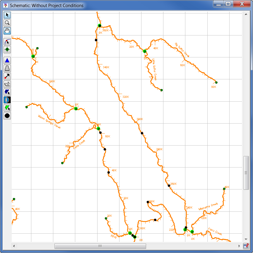
Stream alignments can be created by hand in the map window, imported from an HEC-ResSim model, or imported from a shapefile (*.shp). A stream alignment is a multi-segmented line (default orange line) with beginning and ending stream nodes. A stream node is a location (default dark green points) on a stream that provides stream stationing information. A stream junction is where two streams connect (default bright green point) in a stream alignment.

Common Computation Points (CCP)
Common computation points are locations where data is transferred from one model to another (represented by the black dots in the image below). Common computation points are easiest to use if they are consistently named for all models. The entire study team should be involved in the definition of the common computation points. CCPs loaded in an HEC-WAT study are added to maps by default as black points.
Measures
In USACE Planning practice, a Management Measure is a feature or an activity that can be implemented at a specific geographic site to address one or more planning objectives, and measures can be combined to form Plan Alternatives. As a Planning tool, HEC-WAT provides the option to add measures to the schematic. Measures can be structural, non-structural (flood damage reduction), or ecosystem. Structural measures are physical modifications designed to reduce the frequency of damaging levels of flood inundation, and include dams with reservoirs, levees, channelization measures, walls, diversion channels, pumps, bridge modifications, and ice-control structures. Non-structural measures are activities that reduce flood damage without significantly altering the nature or extent of flooding (e.g., flood proofing, relocation of structures, raising structures). Ecosystem restoration measures are physical modifications or other actions that improve the value and function of an ecosystem (e.g., channel restoration removal of drainage structures or levees).
There are various measures that can be defined for HEC-WAT, but this User Manual will only focus on reservoirs and levees. Other measures available in HEC-WAT are diversions, channel improvements, off-channel storage, and other projects. Measures are not required for an HEC-WAT study.
Impact Areas
An impact area is any distinct portion of a study that is affected by rising or falling stage in a stream, river, lake, or reservoir. The boundaries of an impact area are defined by a closed polygon, and the user can characterize the effects of rising or falling stage by describing the property, project, and/or population at risk in the area bounded by the polygon. Impact areas are an optional element, and are only required when a user wants to compute impacts at damage area centers in the study area, and an HEC-FIA model is part of the HEC-WAT modeling effort.