Viewing and Editing Schematics
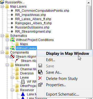
After creating a schematic, the user can view the schematic; edit certain properties of a schematic; save the active schematic; create a copy of an existing schematic; delete a schematic that is not associated with an alternative; and, view an existing schematic's properties. All of these tasks are accomplished through the schematic shortcut menu. To access the schematic shortcut menu, from the Schematic tab, right-click on an existing schematic (e.g., Without Levee) under the Schematics folder, and the schematic shortcut menu will appear.

View a Schematic
To view a schematic in a map window:
- In the Study Pane, with the Schematic tab selected, right-click on a schematic to open the schematic's shortcut menu.
- From the schematic's shortcut menu click Display in Map Window.
- If there is not a map window open in the Desktop Pane, the map window for the selected schematic (e.g., Without Levee) will open in the Desktop Pane. From the schematic map window the user needs to review the new schematic to see if any adjustment needs to be made to the stream alignment; or if measures, CCPs, and/or impact areas need to be added, edited, or deleted.
- If a map window is open in the Desktop Pane, the Select Map dialog box will open. From the Select Map dialog box the user can choose to open the selected schematic in the existing map window or in a new map window. Click OK, the Select Map dialog box will close, and the map window for the selected schematic (e.g., Without Levee) will appear in the Desktop Pane. From the schematic map window the user needs to review the new schematic to see if any adjustment needs to be made to the stream alignment; or if measures, CCPs, and/or impact areas need to be added, edited, or deleted.
Edit an Existing Schematic
To edit the description, or to add and remove measures from an existing schematic:
- From the schematics shortcut menu click Edit. The Schematic Editor will open.

- In the Description box the user can edit the description of schematic.
- From the Measures box the user can add or remove measures from a schematic by selecting the measures (check the checkbox in the Selected column). For example, if the user decides that the selected schematic (e.g., Without Project Conditions) should not to include the Lake Sonoma measure, then from the Measures table, to deselect Lake Sonoma uncheck the checkbox from the Selected column. Click OK to save the change and close the Schematic Editor, or click Apply and keep the Schematic Editor open. Either way, Lake Sonoma will now be removed from the schematic.
- From the Schematic Editor, there is the ability to edit other schematics by using the navigator buttons in the Navigator Bar (located in the upper right-hand corner of the editor).
- Click the
 to navigate to the first schematic, or click the
  to navigate to the last schematic.
 - Alternatively, click the
 and
and buttons to navigate backward and forward one schematic at a time in the list of schematics, respectfully.
 - The center of the navigator button (e.g., 1 of 1) indicates the number of schematics and which schematic the user is presently accessing.
- Click the
- Click OK, the Schematic Editor will close, and if the map window associated with the schematic is open, the measure will no longer display in the map window.
Save a Schematic
To save the active schematic, from the schematic shortcut menu, click Save. Any changes that have occurred to the selected schematic will be saved by HEC-WAT.
Make a Copy of an Existing Schematic
To make a copy of an existing schematic:
- From the schematics shortcut menu, click Save As. The Save Schematic As dialog box will open.

- The information displayed in the dialog box represents the schematic the user has chosen to make a copy of.
- In the Name box, enter the name (required) of the new schematic, and in the Description box, enter a description (optional, but recommended).
- Click OK, the Save Schematic As dialog box will close, and in the Study Pane; under the Schematics folder the new schematic name will appear.
Delete a Schematic
A schematic can only be deleted as long as it is not associated with an alternative. If the schematic is associated with an alternative the Delete from Study command does not display on the schematic shortcut menu. To delete a schematic not associated with an alternative:
- From the Schematic tab, on the Study Pane, from the Schematics folder, right-click on a schematic that is not associated with an alternative. From the Schematics shortcut menu, click Delete from Study.
- A Confirm Manager Delete message window will open, asking for confirmation that the user wants to delete the selected schematic. Click Yes, the schematic name will no longer appear under the Schematics folder on the Study Pane.
Schematic Properties
The properties of a schematic include the name; description; when the schematic was modified; who created the schematic; when the schematic was created; and, the file that contains the schematic data. To view the properties of a schematic, from the schematics shortcut menu, click Properties. The Properties for Schematic Name dialog box will open.

Export Schematic Layers
The user can export schematic sub-layers:
- From the Schematic tab, on the Study Pane, from the Schematics folder, right-click on a schematic. From the Schematics shortcut menu, click Export Schematic.
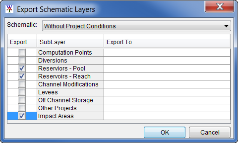
- The Export Schematic Layers dialog box will open.
- From the Export column select the individual sub-layers that need to be exported to a shapefile. Double-click in the associated cell for a sub-layer, under the Export To column. In that cell, either enter the name of the directory where to store the shapefile, or click
 , and an Export browser will open.

- The browser name will be based on the schematic sub-layer that the user has chosen. For example, from the Export Schematic Layers dialog, check to export the Computation Points and click the browse to button and the Export Computation Points to browser window opens. Navigate to the directory where the shapefile will be stored, enter a name in the File name box, click Save. The Export browser will close.

- From the Export Schematic Layers dialog box, click OK. The Export Schematic Layers dialog box will close and the shapefile (all necessary files) will be created in the selected location.