Download PDF
Download page Parameterizing the Magat River Basin Model.
Parameterizing the Magat River Basin Model
Return to Delineating the Magat River Basin Model
Last Modified: 2023-06-20 15:30:08.859
Software Version
HEC-HMS version 4.11 was used to create this tutorial. You will need to use HEC-HMS version 4.11, or newer, to open the project files.
Project Files
If you are continuing from Delineating the Magat River Basin Model you can continue to use your current project files. Otherwise download the initial project files here:


Rename Basin Elements
The delineated basin elements have automatically generated names. Use the Rename Basin Elements utility to provide project-specific names.
- In the Watershed Explorer, right click on the MagatRv basin model and select the Rename Basin Elements menu item.
- Rename the basin elements corresponding to the table below.
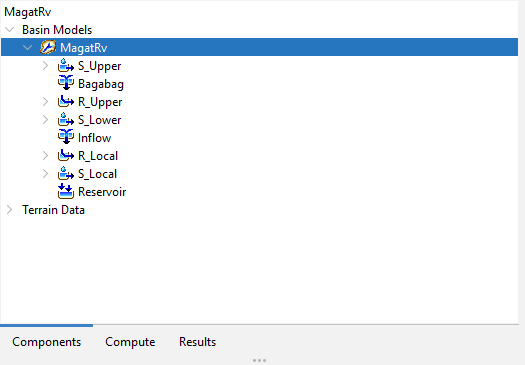
Current Name New Name Subbasin-3 S_Upper Junction-2 Bagabag Reach-2 R_Upper Subbasin-2 S_Lower Junction-1 Inflow Reach-1 R_Local Subbasin-1 S_Local Sink-1 Reservoir 
- Click Apply. The basin elements are now renamed using project-specific identifiers.
Parameterize the Basin Elements
Select the MagatRv basin model node in the Watershed Explorer:
Discretization
- With the MagatRv basin model node selected, from the Parameters menu, select Discretization | Change Method.
- Select Structured.
- Click Change to set all subbasins to use the Structured discretization method.
- With the MagatRv basin model node selected, from the Parameters menu, select Discretization | Structured.
Set Structured discretization parameters according to the table below:
Subbasin Projection Cell Size (meters) S_Upper UTM 51 N 2000 S_Lower UTM 51 N 2000 S_Local UTM 51 N 2000 - Click Apply, then Close to commit the edits.
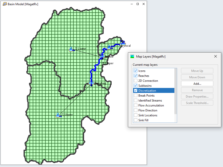
- From the GIS menu, select Compute | Grid Cells to compute grid cell geometries.
Once grid cells are computed, you can visualize this discretization by enabling the Discretization map layer:
Canopy
- With the MagatRv basin model node selected, from the Parameters menu, select Canopy | Change Method.
- Select Simple Canopy.
- Click Change to set all subbasins to use the Simple canopy method.
- With the MagatRv basin model node selected, from the Parameters menu, select Canopy | Simple Canopy.
Set Simple canopy parameters according to the table below:
Subbasin Initial Storage (%) Max Storage (MM) Crop Coefficient Evapotranspiration Uptake Method S_Upper 0 5 1.0 Wet and Dry Periods Simple S_Lower 0 5 1.0 Wet and Dry Periods Simple S_Local 0 5 1.0 Wet and Dry Periods Simple - Click Apply, then Close to save the edits.
Loss
- With the MagatRv basin model node selected, from the Parameters menu, select Loss | Change Method.
- Select Deficit and Constant.
- Click Change to set all subbasins to use the Deficit & Constant loss method.
- With the MagatRv basin model node selected, from the Parameters menu, select Loss | Deficit and Constant.
Set Deficit and Constant loss parameters according to the table below:
Subbasin Initial Deficit (MM) Maximum Storage (MM) Constant Rate (MM/HR) Impervious (%) S_Upper
5 100 2 0.0 S_Lower 5 100 2 0.0 S_Local 5 100 2 0.0 - Click Apply, then Close to save the edits.
For more detail regarding the various Loss methods within HEC-HMS, including discussions on parameterization, see Applying Loss Methods within HEC-HMS.
Transform
- With the MagatRv basin model node selected, from the Parameters menu, select Transform | Change Method.
- Select ModClark.
- Click Change to set all subbasins to use the ModClark transform method.
- With the MagatRv basin model node selected, from the Parameters menu, select Transform | ModClark.
Set ModClark transform parameters according to the table below:
Subbasin Time of Concentration (HR) Storage Coefficient (HR) S_Upper
5 5 S_Lower 5 5 S_Local 2 2 - Click Apply, then Close to save the edits.
For more detail regarding the Clark unit hydrograph Transform method, including discussions on parameterization, see Estimating Clark Unit Hydrograph Parameters and Estimating Parameters with GIS Datasets.
Baseflow
- With the MagatRv basin model node selected, from the Parameters menu, select Baseflow | Change Method.
- Select Linear Reservoir.
- Click Change to set all subbasins to use the Linear Reservoir baseflow method.
- With the MagatRv basin model node selected, from the Parameters menu, select Baseflow | Linear Reservoir.
Set Linear Reservoir baseflow parameters according to the table below:
Subbasin Number of Layer Initial Type GW 1 Initial (M3/S/KM2) GW 1 Fraction GW 1 Coefficient (HR) GW 1 Reservoirs S_Upper
1 Discharge Per Area 0.01 1
20
1
S_Lower 1 Discharge Per Area 0.01 1 20
1
S_Local 1 Discharge Per Area 0.01 1 20 1 - Click Apply, then Close to save the edits.
For more detail regarding the various Baseflow methods within HEC-HMS, including discussions on parameterization, see Applying Baseflow Methods in HEC-HMS.
Reach Routing
- With the MagatRv basin model node selected, from the Parameters menu, select Routing | Change Method.
- Select Lag.
- Click Change to set all reaches to use the Lag routing method.
- With the MagatRv basin model node selected, from the Parameters menu, select Routing | Lag.
Set Lag routing parameters according to the table below:
Subbasin Initial Type Lag Time (MIN) R_Upper
Discharge = Inflow 180
R_Local
Discharge = Inflow 60
- Click Apply, then Close to save the edits.
For more detail regarding the various Reach Routing methods within HEC-HMS, including discussions on parameterization, see Applying Reach Routing Methods within HEC-HMS.
Add Observed Flow at the Bagabag Junction
For more in depth coverage of adding observed flow, see Viewing Observed Flow
Create Time-Series Data
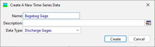
- In HEC-HMS, select Components | Create Component | Time Series Data.
- Name the Time-Series Data Bagabag Gage.
- In the Watershed Explorer, select the Bagabag Gage Discharge Gage node.
- In the Component Editor, specify DSS Filename as <path to>/observed.dss, and specify DSS Pathname as //MAGAT/FLOW/31Dec2008 - 01Jan2011/1Day//.
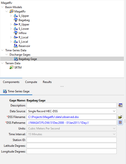
- Click the program Save button.
It is best practice to store project files internal to the project directory. In this example we have moved observed.dss to <MagatRv project directory>/data/observed.dss.
Add Time-Series Data to Basin Element
Streamflow data was gathered from Philippines' Department of Public Works and Highways Streamflow Management System.
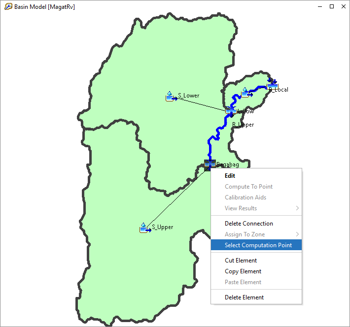
- In the Basin Map, right-click on the Bagabag junction and mark it as a computation point.
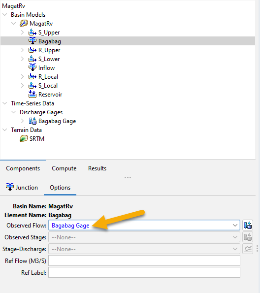
- In the Component Editor, for the Bagabag junction, set the Observed Flow gage to Bagabag Gage.
Summary
The basin model has been parameterized using initial parameter estimates. Further calibration of model parameters is necessary for a production forecasting model. The basin model is now ready for simulation with meteorologic boundary conditions.
Continue to Creating Boundary Conditions for the Magat River Basin Model