Creating the Default Schematic
When a new study is created in HEC-WAT, a default (base) alternative is created with either an HEC-WAT default name (Without Project Conditions) or a user-defined name. A schematic is automatically created with the default alternative using the same name selected by the user.
This default schematic needs the basic schematic elements - stream alignment, common computation points, measures (reservoirs, levees), and impact areas to be defined by the user. Schematic elements and/or measures can be imported from a shapefile (only for the stream alignment, common computation points, reservoirs, levees or impact areas) or added manually in the schematic map window (using the Schematic Map Tools). The steps to define the default schematic are outlined in the following sections. Note, the steps for defining schematic elements also include instructions for creating additional alternative measures (e.g., diversions, channel modifications, off-channel storage areas, other project elements).
Create a Stream Alignment
A stream alignment is a one-dimensional river coordinate system, which defines the natural downstream flow network. Stream alignments are composed of a series of streams, stream nodes, and stream junctions. Stream alignments define stream stationing for the study area.
Import Stream Alignment from a Shapefile
To import a stream alignment:
- Click the Maps tab in the HEC-WAT main window.
- Right-click on Stream Alignment map layer in the Map Layers tree, and the shortcut menu opens.
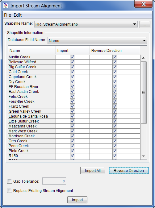
- Click Import in the Stream Alignment map layer shortcut menu. This command elicits the Import Stream Alignment dialog box.
- Alternatively, from the HEC-WAT main window, from the Maps menu, select Import>Stream Alignment. Either option opens the Import Stream Alignment dialog box.
- Select the shapefile that represents the stream centerline for this study from the Shapefile Name list. The Shapefile Name list is populated with all polyline shapefiles in the maps directory of the study. By default, the first element in the list is selected.
- Select the field from the shapefile database file that represents the stream names in the Database Field Name list. The table below the Database Field Name list populates with the attribute for each line feature contained in the shapefile.
- By default, all continuous stream segments will be checked
 in the Import column. In other words, if a checkbox is not selected
  the stream segment is not continuous and will not be imported.
- By default, all continuous stream segments will be checked
- Click the Import All button to automatically check
 the checkboxes in the Import column to select all stream names in the selected shapefile.
 - Click the Reverse Direction button to automatically check
 the checkboxes in the Reverse Direction column to select all stream names in the selected shapefile to be imported with a reverse stream stationing (use this option when the flow direction in the shapefile is not correct).
 - If the selected shapefile has breaks in the polyline feature, check the checkbox to enable the Gap Tolerance option and enter the tolerance value (units for the gap tolerance must match the selected shapefile's horizontal coordinate system).
- Click the checkbox to Replace Existing Stream Alignment to import the selected stream elements. Use this option to replace stream elements in an existing stream alignment; for example, if a stream element was modified and needs to be replaced.
- Click Import, the Import Stream Alignment dialog box will close and the stream alignment imports. A message window appears when the stream alignment is imported successfully. The stream alignment is added to the active map window as an orange stream with dark green stream nodes and bright green stream junctions. Stream stationing is downstream to upstream (downstream stations are less than upstream stations).
Create Stream Alignment in a Schematic Map Window
Stream alignments can also be entered by hand in a schematic map window. To create the stream alignment (or add stream segments to an existing stream alignment):
- From the active schematic map window, from the schematic map toolbar, select the Stream Alignment tool
 .
. - In the schematic map window, hold down the CTRL key, and click on the location to start the stream alignment (draw the stream upstream to downstream).
- Each click creates a vertex point along the stream.
- When reaching the end point of the stream (at the downstream end or at the intersection of an existing stream), release the CTRL key, and click.
- A Create New Stream dialog opens and asks the user to name the new stream. Enter a name in the Name box and click OK to close the Create New Stream dialog box.
- If the new stream ended on top of an existing stream a Connect Stream Reaches dialog opens.
- Click Yes to add a junction and connect the two streams. The new stream will appear in the schematic map window labeled with the entered name and connected with a junction (and a stream node) to the existing stream.
- Click No and a Stream Reaches Intersect dialog will open, requiring users to confirm that the stream should not be connected to the reach. Click No to create the new stream without connecting to an existing stream reach. The new stream will appear in the schematic map window labeled with the entered name and ended with a stream node.
- Commands available for editing an existing stream are available by selecting the Stream Alignment tool
 , and right-clicking on a stream element.
Add Common Computation Points (CCPs)
Common computation points (CCPs) represent locations where one model can transfer data to another model.
Import CCPs from a Shapefile
To import CCPs from a shapefile (*.shp):
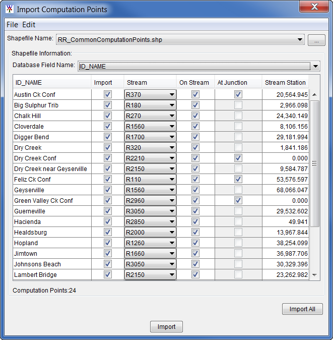
- From the HEC-WAT main window, from the Maps menu, select Import>Computation Points. This elicits the Import Computation Points dialog box.
- Select the shapefile that represents the common computation points from the Shapefile Name list or browse to the correct point shapefile using the browse button to the right of the list box. The Shapefile Name list is populated with all point shapefiles the maps directory of a study, and defaults to the first item in the list of point shapefiles.
- Select the column that represents the names of the CCPs from the Database Field Name list. This list is populated by all columns in the database file associated with the selected shapefile. The table below the Database Field Name list populates with the point features contained in the shapefile. If there is an issue with any of the CCPs, the
 checkbox in the Import column will not be selected.
 - Click Import, the Import Computation Points dialog box closes and the CCPs are imported. A message window appears when the CCPs have imported. The CCPs are added to the active map window as black circles.
Add CCPs in a Schematic Map Window
A user can also add CCPs to the schematic manually in the schematic map window by performing the following steps:
- From the the active schematic map window, from the schematic map toolbar, select the Computation Point
 tool.
tool. - Hold down the CTRL key and click on the schematic to place the common computation point.
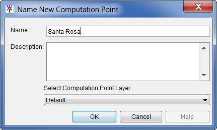
- The Name New Computation Point dialog box opens.
- Enter the new Name (required) and Description (optional, but recommended).
- Click OK, the Name New Computation Point dialog box closes.
- The new CCP appears as a black circle in the schematic window.
However, if a CCP is added directly at a stream junction, a slightly different Name new Computation Point dialog box opens.
- Enter the new Name (required) and Description (optional, but recommended).
- From the Select the Placement of the Computation Point list, define the placement of the CCP. The user can place the CCP on the stream junction, along one of the streams that form the stream junction, or none of the above. For example, in the image below, the CCP will be placed on the stream junction.
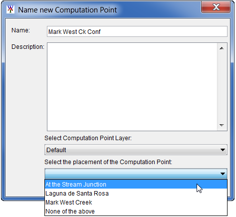
- Click OK, the Name new Computation Point dialog box closes.
- The new CCP will now appear in the map window as a black circle.
Add a Reservoir
A reservoir is the impoundment created behind a dam. To add a reservoir:
- Select the Reservoir tool
 , from the schematic map window toolbar.
 - Hold down the CTRL key and click on the stream alignment to place the upstream end of the reservoir.
- Release the CTRL key; drag the mouse to the downstream end of the reservoir and click.
- The Name New Reservoir dialog box opens.
- Enter a Name (Lake Mendocino) and Description (optional, but recommended) for the reservoir.
- Click OK, the Name New Reservoir dialog box closes.
- The reservoir now appears on the schematic as a cyan triangle (reservoir pool), a blue line (storage reach), a gray rectangle (dam), and two CCPs that represent the upstream and downstream ends of the reservoir.

The default representation of the reservoir pool is a triangle; the user can edit this triangle if a more detailed representation of the pool is desired.
- With the Reservoir tool
 pressed, double-click on the reservoir. The triangle changes green with a blue outline color to signify edit mode. Three vertex points (blue) appear at the vertices and the reservoir label represented by a yellow circle appears at the apex of the triangle.
 - Shift and click along the border of the reservoir to add vertices.
- Select a vertex to move it to change the shape of the reservoir (reservoir shapes do not change computation behavior).
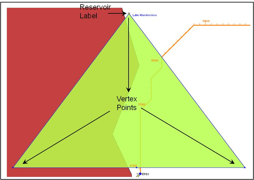
When a reservoir is created two CCPs are created with default names. It is recommended that the names of the two CCPs be changed. These two CCPs represent the inflow and outflow junctions of the reservoir and should be renamed accordingly.
To change the name of a CCP:
- Select the
 Computation Point tool, from the schematic map window toolbar.
 - Right-click on the CCPs of interest.
- From the shortcut menu, click Rename Computation Point.
- The Rename Computation Point dialog box opens.
- Enter the new name in the Name box (e.g., Lake Mendocino Inflow Jct).

- Click OK, a Confirm Rename window opens, asking the user to be sure that the CCP is to be renamed.
- Click Yes, the Rename Computation Point dialog box will close and the new name for the CCP will appear in the map window.
Add Impact Areas
An impact area describes a geospatial area of impact. Impact areas are an optional element, and are only required when the user wants to aggregate impacts in the study area.
Import Impact Areas from a Shapefile
To import impact areas from a shapefile (*.shp):
- From Maps menu in the WAT main window select Import>Impact Areas. This elicits the Import Impact Areas dialog box.
- Select the shapefile that represents the impact areas for this study from the Shapefile Name list. The Shapefile Name list is populated with all polygon shapefiles in the maps directory of the study. By default to the first element in the list is selected.
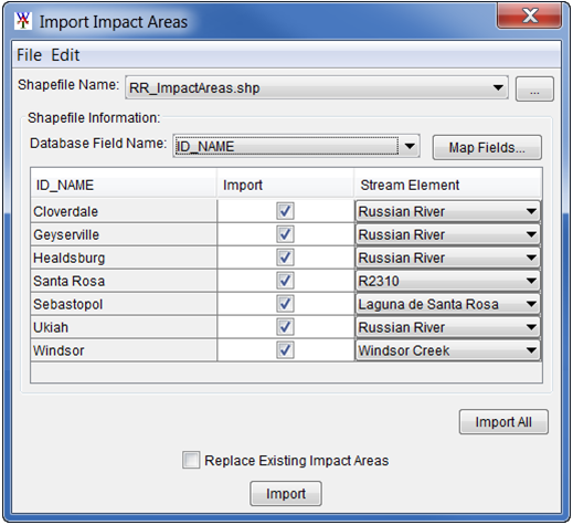
- Select the field name in the attribute file that contains the names of the impact areas from the Database Field Name list. The table below the Database Field Name populates with the features contained in the shapefile. If there is an issue with any of the impact areas the checkbox in the Import column will not be selected.
- Click Import, the Import Impact Areas dialog box closes.
- A message window appears when the impact areas have been imported successfully.
- In the active map window the impact areas appear as green polygons.
Add Impact Areas in a Schematic Map Window
Impact areas can also be added to a schematic map window by hand. To add impact areas by hand:
- Select the Impact Area tool
 , from the schematic map window toolbar.
 - In the schematic map window, hold down the CTRL key while clicking the mouse button. Each click creates a vertex point, which is the boundary of the polygon. When reaching the end point, release the CTRL key and click.
- The user will be asked to name the impact area. After naming the impact area, the impact area will appear on the active map window.
- Commands available for editing an existing impact area are available by selecting the Impact Area tool, and right-clicking on an impact area.
Additional Alternative Measures
Additional alternative measures include levees, diversions, channel modifications, off-channel storage areas and other projects (e.g., pump stations). Alternative measures can be added to the default schematic or to additional schematics (Creating Additional Schematics provides instructions for creating additional schematics).
Add a Levee
Levees can be imported from a shapefile or added by hand in the schematic map window.
Import Levees from a Shapefile
To import a levee from a shapefile:
- From Maps menu, from the HEC-WAT main window select Import>Levees. This command opens the Import Levees dialog box.
- From the Shapefile Name dropdown menu select the appropriate shapefile (if the shapefile has been added as a map layer; e.g., levee.shp). The Shapefile Name list is populated with all polygon shapefiles in the maps directory of the study. By default to the first element in the list is selected.
Alternatively, click the browse to button, from the Choose Shapefile browser window navigate and select the appropriate shapefile (*.shp), and click Open.
 - From the Database Field Name dropdown list select the appropriate field name containing the levee identification (e.g., Id), and the table updates with the features (e.g., WF_RR_Levee) contained in the shapefile.
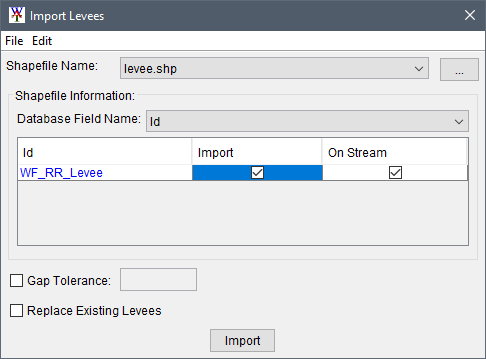
- To import a listed levee, make sure the Import
 checkbox is checked for the desired levee(s). Also, check the checkbox in the On Stream column to import the levee(s) on the stream alignment.
Add a Levee in a Schematic Map Window
Levees can also be added to a schematic by hand. To add a levee by hand:
- A levee has to be started on the stream alignment. To create a levee, select the Levee
 tool, hold down the CTRL key, and click on the stream alignment to add a line starting vertex. Move the mouse cursor to the ending vertex point for the levee and click the location. The levee will only have a starting vertex (on the stream alignment) and a ending vertex point.
 - The Name New Levee dialog box opens. Enter a name for the levee in the Name box (required), add a description in the Description box (optional, but recommended).
- Click OK and the levee will be added to the schematic as a bold black line along the stream alignment.
- Commands available for editing an existing levee are available by selecting the Levee tool, and right-clicking on a levee.
Add a Diversion
Diversions can only be added by hand in the schematic map window. A diversion has to be started on the stream alignment. To create a diversion, select the Diversion tool, hold down the CTRL key, and click on the stream alignment. Each click creates a vertex point along the diversion. When reaching the end point of the diversion, release the CTRL key, and click. The user will be asked to name the diversion. After naming the diversion, the diversion will appear on the active map window. Commands available for editing an existing diversion are available by selecting the Diversion tool, and right-clicking on a diversion.
Add Channel Modifications
A channel modification can only be added by hand in the schematic map window. A channel modification has to be created on the stream alignment. To create a channel modification, select the Channel Modification tool, hold down the CTRL key, click on the upstream end of the channel modification, release the CTRL key, and drag along the stream alignment to the downstream end of the channel modification and click. The user will be asked to name the channel modification. After naming the channel modification, the channel modification will appear on the active map window. Commands available for editing an existing channel modification are available by selecting the Channel Modification tool, and right-clicking on a channel modification.
Create an Off-Channel Storage Area
Off-channel storage areas can only be added manually in the schematic map window. To create an off-channel storage area, select the Off-Channel Storage Area tool and hold down the CTRL key while clicking the mouse button. Each click creates a vertex point, which is the boundary of the polygon. When reaching the end point, release the CTRL key and click. The user will be asked to name the off-channel storage area. After naming the off-channel storage area, the off-channel storage area will appear on the active map window. Commands available for editing an existing off-channel storage area are available by selecting the Off-Channel Storage Area tool, and right-clicking on an off-channel storage area.
Add an Other Project Element
The Other Project tool is only available from the schematic map window toolbar. This tool allows users to add other project elements (e.g., pump stations) to the schematic. To create an "other" project, select the Other Project tool and hold down the CTRL key and click. The user will be asked to name the "other" project. After naming the "other" project, the "other" project will appear on the active map window. Commands available for editing an existing "other" projects are available by selecting the Other Project tool, and right-clicking on an "other" project.